Prepared by the DeFa Engineering Team Published Updated
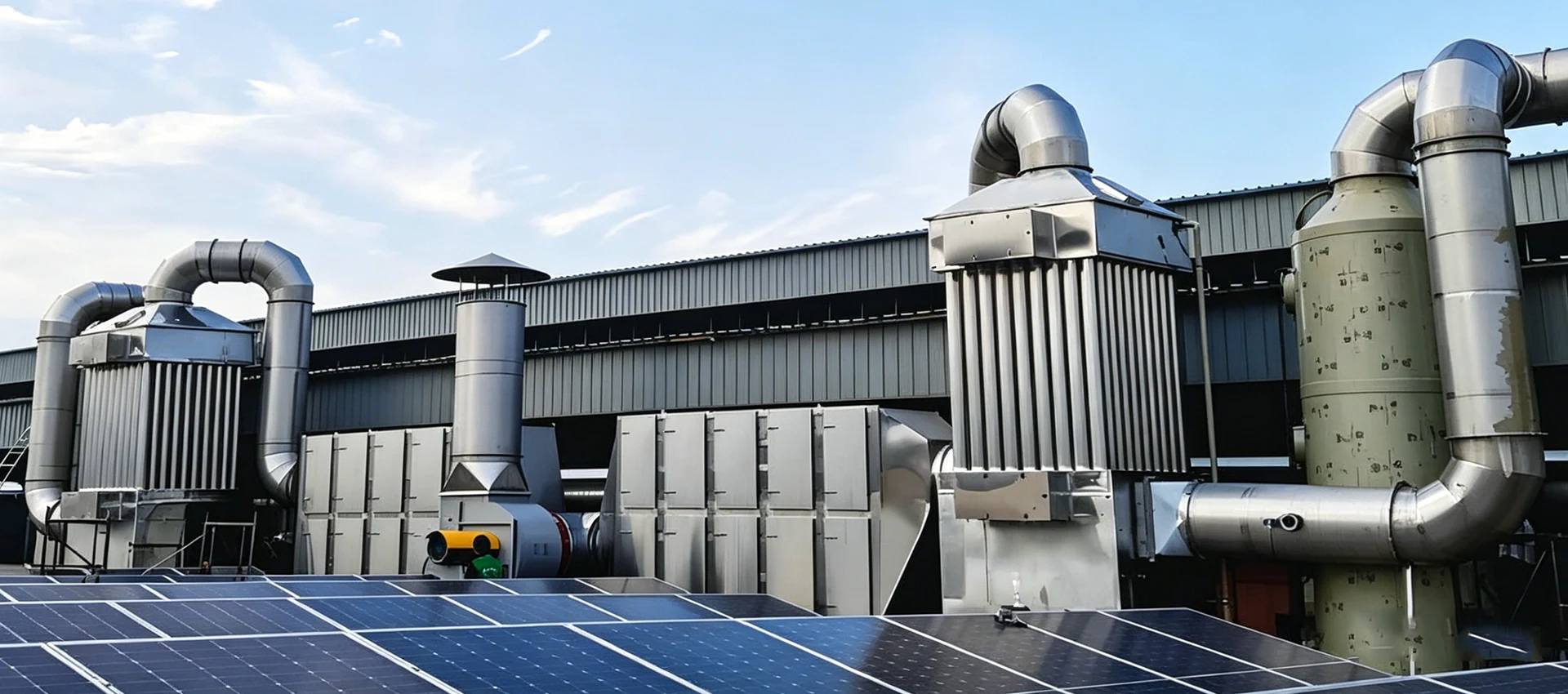
Quick answer
There is no universal “best” industrial VOC treatment method. The right system depends on the actual exhaust stream: airflow, VOC concentration and mass loading, chemical composition, temperature, humidity, particulate or acid-mist content, operating schedule, safety constraints and the emission limit in the facility’s permit. Thermal and catalytic oxidizers destroy VOCs; activated carbon and zeolite systems capture them; condensers recover suitable compounds; wet scrubbers absorb soluble gases; and plasma or biological systems may suit selected low-concentration or odor-driven applications. Complex exhaust normally needs a treatment train rather than one device.
What are industrial VOCs?
“VOC” is a regulatory and engineering category, not the name of one chemical. Under the U.S. Clean Air Act definition, volatile organic compounds are carbon compounds that participate in atmospheric photochemical reactions, subject to listed exclusions for compounds with negligible reactivity. Different jurisdictions may define and measure VOCs differently, so a project should use the definition written into its applicable rule or operating permit. See the U.S. EPA definition of VOC.
Industrial VOC emissions can come from solvents, coatings, inks, adhesives, resins, cleaning agents, fuel handling, chemical reactions and the heating of plastics, oils or other organic materials. In the atmosphere, VOCs can react with nitrogen oxides in sunlight to form ground-level ozone. The EPA’s ground-level ozone overview identifies industrial facilities, chemical plants, refineries and combustion sources among the contributors.
The treatment decision must be based on individual compounds as well as total VOC concentration. A stream dominated by recoverable solvent vapor behaves differently from one containing halogens, sulfur compounds, silicone, sticky aerosols or fluctuating mixtures. Those differences affect materials of construction, pretreatment, fire protection, catalyst suitability, adsorbent life and the choice of monitoring method.
Start with the exhaust stream, not the equipment catalog
A useful proposal starts with measured process data. Airflow alone is not enough, and a single concentration reading taken during a quiet production period can lead to an undersized system. Sample representative operating states: startup, normal production, product changeover, cleaning, peak solvent use and shutdown where relevant.
| Input | Why it matters | Useful form |
|---|---|---|
| Airflow | Sets duct, fan and equipment size and strongly affects energy use. | Normal, minimum and maximum m³/h or scfm |
| VOC concentration | Helps determine mass loading, destruction or recovery duty and fuel demand. | Inlet profile in mg/m³, ppmv or g/Nm³ |
| Chemical composition | Determines adsorbability, condensability, catalyst compatibility, corrosion and byproducts. | Compound list, SDS data and laboratory analysis |
| Temperature and humidity | Affect adsorption, condensation, corrosion, plasma stability and pretreatment. | Normal range and peak conditions |
| Co-pollutants | Dust, oil mist, acid mist, alkali, moisture and aerosols can damage the main VOC stage. | Concentration, particle size and droplet characteristics |
| Operating schedule | Continuous and intermittent sources have different heat, regeneration and standby needs. | Hours/day, days/year and batch cycle |
| Required outlet | Defines the real removal duty and monitoring plan. | Permit limit, test method and averaging period |
| Site constraints | Space, utilities, climate, noise and access can eliminate otherwise suitable options. | Layout, utility capacity and maintenance clearance |
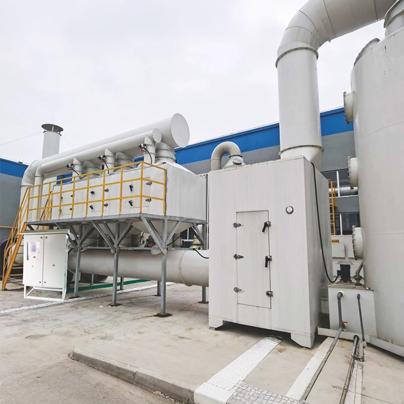
A reliable VOC system is usually a treatment train
Industrial exhaust rarely arrives as a clean mixture of air and one solvent. The gas may carry overspray, oil droplets, condensable tar, dust, acid mist or water vapor. Sending that mixture directly into the main VOC device can foul a heat exchanger, poison a catalyst, saturate carbon, corrode electrodes or create unsafe deposits.
- Reduce and contain emissions at the source. Review raw materials, lids, seals, cleaning practices and enclosure before increasing the size of the downstream system.
- Capture the exhaust. Use an enclosure or hood that contains the plume without pulling unnecessary room air into the duct.
- Condition the gas. Remove dust, oil mist, droplets or acid aerosols and adjust temperature or humidity when the main device requires it.
- Recover or destroy the VOCs. Apply the method selected from measured stream data.
- Polish when necessary. A secondary stage can handle residual odor, fine mist or short concentration peaks.
- Monitor the process. Track the parameters that show whether collection and treatment are working between formal stack tests.
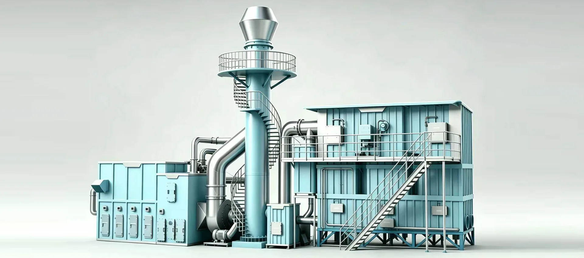
Industrial VOC treatment methods
1. Regenerative thermal oxidation (RTO)
A thermal oxidizer raises the exhaust to a temperature at which organic compounds oxidize to carbon dioxide and water. Temperature, residence time and mixing are the core design factors. An RTO alternates hot and cool gas through ceramic media to recover heat, reducing the auxiliary fuel required compared with a non-regenerative thermal oxidizer. The EPA thermal oxidizer guidance describes both regenerative and recuperative heat recovery.
RTO is commonly considered for continuous, medium-to-high VOC mass loads and mixed organic streams where recovery is not practical. It becomes less attractive when the exhaust is extremely dilute, highly intermittent or contaminated with compounds that can create corrosive combustion products or deposits. Pretreatment, materials selection and a process-safety review are essential.
See DeFa’s regenerative thermal oxidizer equipment for a product-level overview. Project performance must be confirmed against the actual gas analysis and written design conditions.
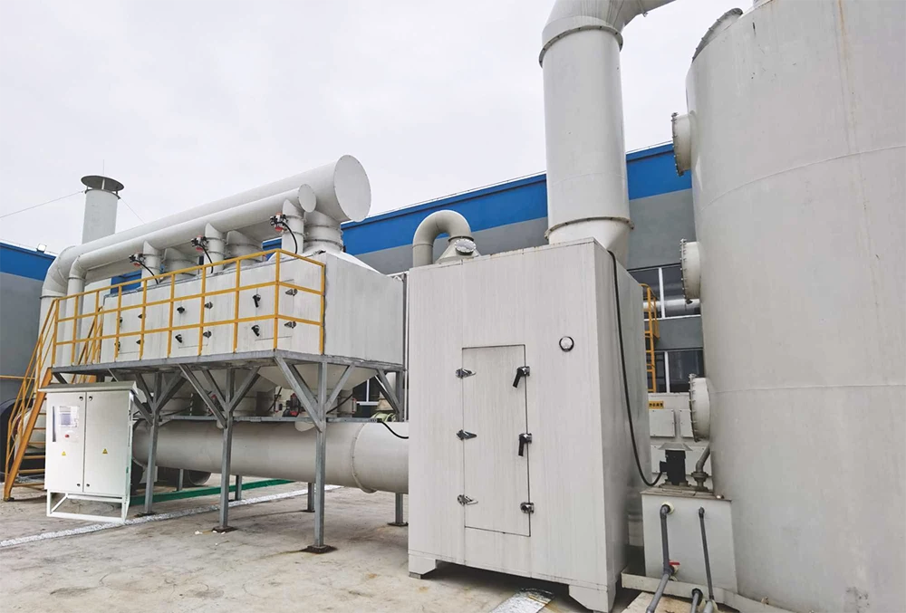
2. Catalytic oxidation
Catalytic oxidizers use a catalyst to accelerate oxidation, allowing operation at a lower temperature than conventional thermal oxidation. This can reduce fuel demand when the exhaust is compatible with the catalyst. The trade-off is sensitivity: catalyst performance depends on VOC species, operating temperature and the presence of masking or poisoning agents. The EPA catalytic oxidizer guidance recommends tracking outlet VOC concentration, catalyst-bed inlet temperature and catalyst activity.
Catalytic oxidation is best evaluated when the gas composition is predictable and pretreatment can keep dust, oil, heavy metals, sulfur, halogens or other catalyst-deactivating material away from the bed. A catalyst compatibility review is more reliable than selecting the system from a generic VOC concentration range.
3. Activated carbon adsorption
Adsorption transfers VOC molecules from the gas to a solid surface. Activated carbon is the most common adsorbent, although zeolites and other media may be used. Carbon systems are often practical for lower mass loads, intermittent processes, odor polishing or applications where thermal equipment is difficult to justify.
Every adsorbent has finite capacity. When the bed approaches breakthrough, the media must be replaced or regenerated. High humidity, elevated temperature, incompatible compounds, dust and concentration peaks can shorten the service interval. EPA identifies outlet VOC concentration, bed temperature, gas flow, inlet concentration, moisture and pressure differential as relevant indicators for an activated carbon adsorber.
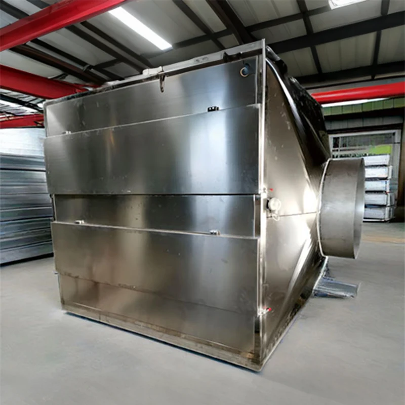
DeFa’s activated carbon box equipment can be considered as a standalone low-load device or as a polishing stage in a multi-stage system. Media type, bed depth, residence time and replacement plan should be specified for the target compounds.
4. Zeolite concentration
A zeolite rotor or concentrator transfers VOCs from a large, dilute exhaust stream into a smaller, more concentrated desorption stream. The concentrated stream is then sent to an oxidizer or another recovery device. This arrangement can make treatment of high-airflow, low-concentration exhaust more economical because the final destruction device handles less total gas volume.
Zeolite concentration is not a universal front end. High-boiling compounds, sticky aerosol, dust and incompatible chemistry can foul or damage the rotor. The desorption temperature, concentration ratio, removal target and downstream oxidizer must be designed as one system.
5. Condensation and solvent recovery
Condensation cools or compresses a gas stream so suitable vapors become liquid. It is most attractive for relatively concentrated streams containing recoverable compounds with favorable condensation characteristics. Recovery may reduce raw-material loss, but the recovered liquid still needs safe storage, quality evaluation and reuse or disposal planning.
A condenser is often followed by adsorption or oxidation because it may not reach a low outlet concentration by itself. Variable composition, water vapor and freezing or fouling risks must be included in the design.
6. Wet scrubbing and wet electrostatic precipitation
A wet scrubber brings the exhaust into contact with a liquid. It is well suited to soluble gases, acid or alkaline contaminants and some combined gas-and-particle duties. It is not automatically an effective destruction method for poorly soluble organic compounds. Scrubbing liquid chemistry, gas-to-liquid contact, pressure drop, pH, blowdown and wastewater treatment all matter. EPA’s wet scrubber guidance identifies liquid flow, pressure differential and liquid condition as key operating indicators.
Wet electrostatic precipitation can remove fine droplets, oil mist and acid aerosol that would otherwise contaminate an adsorber, catalyst or thermal stage. For mixed acid and VOC exhaust, a scrubber and mist-control stage may be pretreatment rather than the final VOC solution. DeFa’s three-acid waste gas treatment system illustrates this type of multi-stage approach.
7. Low-temperature plasma
Plasma systems use an electrical discharge to generate energetic electrons and reactive species. They can be considered for selected low-concentration, odor-driven or variable streams where a compact, fast-response device is useful. Results depend strongly on gas chemistry, humidity, residence time, energy density, electrode condition and downstream byproduct control.
Treatability testing is advisable before using plasma as the primary control method for a complex VOC mixture. Pretreatment is especially important when the stream contains oil mist, moisture or particulate that can foul the discharge section. See the DeFa plasma deodorization module for the available equipment concept.
8. Biological treatment
Biofilters and biotrickling systems use microorganisms to degrade biodegradable pollutants. They may provide low operating energy for steady, low-concentration odor or organic loads, but the biology needs a stable environment. Temperature, moisture, pH, nutrients, empty-bed contact time and toxic shock loads must be controlled.
Biological treatment is commonly evaluated for wastewater, food processing, organic-waste and other odor sources. It is less suitable for sudden high loads or compounds that are poorly biodegradable or toxic to the biomass. DeFa supplies a PP biological deodorization tower and air duct for corrosion-resistant odor-control applications.
VOC treatment methods compared
| Method | Often considered for | Main advantage | Important constraint | Key operating checks |
|---|---|---|---|---|
| RTO | Continuous mixed VOC streams with meaningful mass loading | Destroys a broad range of compatible organics and recovers heat | Fuel, safety, corrosive byproducts, deposits and high airflow | Chamber temperature, outlet VOC, flow, fuel pressure, CO and O₂ |
| Catalytic oxidizer | Predictable, clean VOC streams | Lower oxidation temperature | Catalyst poisoning, masking and replacement | Bed inlet/outlet temperature, activity, pressure drop and outlet VOC |
| Activated carbon | Lower mass loads, intermittent sources and polishing | Simple capture without a combustion chamber | Breakthrough, moisture, fire risk and spent-media handling | Outlet VOC, bed temperature, humidity and pressure drop |
| Zeolite concentrator | Large airflow with dilute compatible VOCs | Reduces the gas volume sent to the final device | Rotor fouling and compound compatibility | Adsorption/desorption temperature, pressure and removal performance |
| Condensation | Concentrated, recoverable solvent vapor | Potential product recovery | May need a polishing stage; water and mixed solvents complicate recovery | Inlet/outlet temperature, pressure, condensate rate and outlet VOC |
| Wet scrubber | Soluble gases, acid/alkali components and selected pretreatment | Handles corrosive soluble contaminants and can cool the gas | Wastewater, scaling and weak capture of poorly soluble VOCs | Liquid flow, pressure drop, pH, makeup and blowdown |
| Plasma | Selected low-concentration or odor-driven streams | Compact and responsive | Chemistry-specific performance and possible byproducts | Power, electrode condition, humidity, outlet VOC and byproduct checks |
| Biological | Steady biodegradable odor and VOC loads | Low energy when the biology is stable | Footprint, climate, shock loads and biomass management | Moisture, pH, temperature, pressure drop and outlet concentration |
How to estimate VOC mass loading and required removal
Concentration and airflow must be evaluated together. A dilute stream can still carry a large VOC mass when the airflow is high.
VOC mass loading (kg/h) = airflow (m³/h) × concentration (mg/m³) ÷ 1,000,000
Example: an exhaust flow of 20,000 m³/h at 300 mg/m³ carries an estimated VOC load of 6 kg/h. If the permitted outlet is 30 mg/m³ and inlet and outlet conditions use the same basis, the concentration-based minimum removal is 90%. This simple example does not replace a design calculation: gas normalization, oxygen correction, capture efficiency, concentration peaks, measurement uncertainty, speciation and equipment availability may all change the required duty.
Concentration-based removal (%) = (inlet concentration − outlet concentration) ÷ inlet concentration × 100
The control device cannot remove emissions it never captures. A project therefore needs both capture efficiency and device efficiency. It also needs a process-safety review covering flammability, ignition sources, static control, interlocks, emergency bypass philosophy and abnormal production conditions. Do not apply a generic oxidizer or adsorption design to a combustible mixture without qualified safety engineering.
What determines industrial VOC treatment cost?
Published “price per airflow” figures are usually misleading because two systems with the same m³/h can have very different materials, safety equipment, heat duty and pollutant mass loading. The U.S. EPA maintains an Air Pollution Control Cost Manual covering carbon adsorbers, oxidizers, scrubbers and related equipment. A supplier quotation still needs project-specific data.
Capital cost drivers
- Maximum airflow and turndown range
- VOC mass loading and required outlet concentration
- Number of pretreatment and polishing stages
- Stainless steel, PP, FRP or other corrosion-resistant construction
- Heat recovery, solvent recovery and redundancy requirements
- Explosion protection, fire detection, isolation and safety interlocks
- Ductwork, stack, foundations, electrical work and installation access
- Instrumentation, data logging and emissions monitoring
Operating cost drivers
- Natural gas, electricity, steam, cooling water or compressed air
- Activated carbon, catalyst, chemicals, filters and biological media
- Wastewater, spent adsorbent, condensate and hazardous-waste handling
- Fan pressure drop and annual operating hours
- Cleaning, calibration, inspections and unplanned downtime
- Value recovered from solvent or usable waste heat
Compare alternatives on total cost of ownership, not purchase price alone. A low-capital carbon system can become expensive when mass loading causes frequent replacement. An oxidizer with higher capital cost can also be uneconomic if a dilute stream needs continuous auxiliary fuel. The cheapest reliable option is the one matched to the measured process and production schedule.
Monitoring and compliance are part of the design
An emission limit is only one part of compliance. The facility may also need specified test methods, operating ranges, inspections, recordkeeping and reporting. In the United States, requirements can arise from federal rules, state or local rules and the facility’s permit. EPA notes that stationary-source monitoring is used both to demonstrate compliance and to identify control-device problems so operators can take corrective action. See the EPA emissions monitoring FAQ.
Do not assume that a manufacturer’s nominal removal percentage guarantees compliance at every site. Agree on the inlet basis, outlet limit, test method, averaging period, operating envelope, excluded compounds, availability target and consequences of abnormal conditions before purchase. Where third-party stack testing is required, include sampling ports, access platforms and safe test access in the mechanical design.
| Device | Common performance indicators |
|---|---|
| Thermal oxidizer | Combustion chamber temperature, outlet VOC, gas flow, auxiliary fuel pressure, CO and O₂ |
| Catalytic oxidizer | Catalyst inlet/outlet temperature, activity, pressure differential and outlet VOC |
| Carbon adsorber | Outlet VOC, bed temperature, inlet moisture, gas flow, pressure differential and regeneration/replacement status |
| Wet scrubber | Liquid flow, pressure differential, liquid pH or concentration, makeup and blowdown |
Typical VOC treatment trains by industry
The examples below are starting points. The final train should be confirmed from representative sampling and the site’s permit.
Coating, painting and printing
Overspray or ink aerosol should be removed before a carbon bed, zeolite rotor or oxidizer. High-airflow dilute streams may justify concentration before oxidation, while smaller intermittent sources may suit adsorption. Solvent changes and cleaning cycles should be included in the peak-load profile.
Photovoltaic manufacturing
Heating and lamination processes can produce mixed organic vapors with changing loads. Depending on composition and airflow, the train may combine collection, filtration or cooling, concentration and oxidation. Review DeFa’s guide to photovoltaic organic waste gas treatment and the matching photovoltaic VOC treatment equipment.
Heat treatment and quenching
Quenching exhaust may contain oil mist, smoke, particulate, condensable organics and odor. Oil and particle removal normally comes before the main VOC stage. See the detailed quenching exhaust treatment process and DeFa’s quenching waste gas treatment equipment.
Chemical, pharmaceutical and mixed acid processes
Batch changes, corrosive gases and catalyst poisons make speciation especially important. Condensation can recover suitable solvents; scrubbers can remove compatible acid or alkaline gases; mist elimination protects downstream equipment; and adsorption or oxidation can address the remaining organic load. Read the application guide for a three-acid waste gas treatment system.
Plastic processing and recycling
Exhaust composition changes with polymer, additives, contamination and temperature. Smoke and sticky condensables can rapidly foul adsorbents or catalysts, so representative analysis and pretreatment trials are valuable. Avoid designing from “total VOC” alone when the feedstock varies.
Industrial VOC treatment RFQ checklist
Provide the following information when requesting a technical proposal:
- Process description and source of the exhaust
- Normal, minimum and maximum airflow
- VOC compound list and concentration profile
- Temperature, humidity, oxygen and pressure conditions
- Dust, oil mist, acid mist, water droplets or other co-pollutants
- Operating hours, batch cycle and expected production expansion
- Required outlet concentration, removal target and test method
- Available fuel, electricity, steam, water and compressed air
- Site layout, installation environment and maintenance access
- Local safety, permitting, monitoring and redundancy requirements
Need a treatment concept for your exhaust stream?
DeFa Environmental Equipment supplies industrial waste gas treatment equipment, RTO systems, adsorption equipment, plasma modules, scrubbers and intelligent controls. Send your airflow, gas composition, concentration, temperature and required outlet limit for an engineering review.