Prepared by the DeFa Engineering Team
Quick answer
Choose an RTO when the process has a meaningful, reasonably steady VOC mass load, the compounds are suitable for thermal oxidation, and the plant needs continuous destruction rather than routine media replacement. Choose activated carbon when the VOC load is lower or intermittent, the gas is cool and compatible with the selected carbon, and the facility can monitor breakthrough and manage spent or regenerated media. A high-airflow, dilute stream may need source segregation or concentration before either option becomes economical.
There is no reliable universal concentration threshold separating the two. Airflow, VOC composition, annual operating hours, humidity, temperature, peak loading and the required outlet limit can change the answer. For a broader view of available technologies, start with the complete industrial VOC treatment guide.
RTO destroys VOCs; activated carbon captures them
The most important difference is what happens to the pollutant. A regenerative thermal oxidizer raises a compatible VOC-laden gas to its oxidation temperature. With sufficient temperature, residence time and mixing, the organic compounds are converted mainly to carbon dioxide and water. Ceramic media alternately absorb and release heat, reducing the auxiliary fuel required to keep the process hot. The U.S. EPA thermal oxidizer overview identifies temperature, residence time and mixing as the central design factors and describes regenerative heat recovery through fixed ceramic beds.
Activated carbon adsorption is a transfer process. VOC molecules move from the gas to the surface of the adsorbent. Once the bed approaches breakthrough, the carbon must be replaced or regenerated. EPA notes that every adsorbent has a finite pollutant capacity and distinguishes saturation capacity from the earlier breakthrough capacity at which significant pollutant begins to leave the bed. See the EPA activated carbon adsorber guidance.
That distinction affects the entire project. An RTO requires a combustion system, heat balance, safety interlocks and high-temperature maintenance. A carbon system requires an adsorption-capacity basis, breakthrough monitoring and a defined route for carbon replacement, off-site reactivation, on-site regeneration or solvent recovery.
RTO vs activated carbon at a glance
| Selection factor | RTO | Activated carbon adsorption |
|---|---|---|
| Control mechanism | Destroys compatible VOCs by thermal oxidation | Captures VOCs on a finite adsorbent surface |
| Common starting point | Continuous or long-running processes with a meaningful VOC mass load | Lower-load, intermittent or polishing duties with adsorbable compounds |
| Primary design basis | Airflow, VOC heat release, temperature, residence time, mixing and heat recovery | Airflow, compound-specific working capacity, contact time, temperature, humidity and breakthrough |
| Main recurring cost | Auxiliary fuel, fan power, inspections and high-temperature component maintenance | Carbon replacement or regeneration, fan power, testing and spent-media handling |
| Effect of dilute, high airflow | Can increase fuel demand and equipment size | Can require a large bed and create rapid total media use despite a low concentration |
| Effect of intermittent operation | Startup, warm-up and standby energy can weaken the economics | Often easier to match, provided peak load and desorption during idle periods are addressed |
| Co-pollutants | Dust, sticky condensables and acid-forming compounds can foul or corrode the system | Dust, oil mist, moisture and competing compounds can block sites or shorten bed life |
| Routine performance checks | Chamber temperature, outlet VOC, gas flow, CO, oxygen, fuel pressure and pressure drop | Outlet VOC, bed temperature, inlet moisture, gas flow, pressure drop and carbon condition |
| Pollutant after treatment | VOC mass is oxidized; some chemistries may create acid gases or other byproducts requiring control | VOC mass remains in spent carbon, regeneration gas or recovered solvent |
Calculate VOC mass loading before comparing equipment
Concentration by itself is not enough. A low concentration moving through a large exhaust volume can produce a substantial hourly and annual VOC load. Start with normal, minimum and maximum airflow, then combine those measurements with a concentration profile covering normal production, cleaning, changeover and peak-emission steps.
VOC mass loading (kg/h) = airflow (m³/h) × concentration (mg/m³) ÷ 1,000,000
For example, 20,000 m³/h at 100 mg/m³ represents 2 kg/h of VOC entering the control system. At 4,000 operating hours per year, the gross annual inlet load is 8,000 kg. This does not mean that 8,000 kg of carbon will be required: actual carbon use depends on compound-specific working capacity, competitive adsorption, humidity, temperature, the breakthrough limit and regeneration strategy. It does show why a stream described only as "100 mg/m³" can be expensive to treat with disposable media.
Gather these inputs before requesting a comparison:
- Normal, minimum and peak airflow at a defined temperature and pressure basis
- VOC concentration over time, including short batch or cleaning peaks
- Individual VOC compounds and approximate fractions, not TVOC alone
- Gas temperature, relative humidity, oxygen content and flammability data
- Dust, oil mist, paint overspray, acid mist, water droplets and condensables
- Hours per day, days per year, startup frequency and planned production growth
- Required outlet concentration, test method, averaging period and permit conditions
- Available gas, electricity, steam, nitrogen, cooling and waste-handling routes
When an RTO is the stronger candidate
An RTO moves to the front of the shortlist when the plant needs continuous VOC destruction and the incoming mass load can support an efficient heat balance. Coating ovens, printing dryers, chemical process exhaust and other steady solvent-emission sources are common examples, but the process name alone never confirms suitability.
An RTO deserves closer evaluation when:
- The process runs for long, predictable periods rather than a few short batches.
- VOC loading is high enough that regenerative heat recovery can materially reduce auxiliary fuel.
- The solvent mix is variable, but the oxidation products and materials of construction can be safely managed.
- Frequent carbon replacement, storage or disposal would interrupt production.
- The facility needs a destruction method rather than solvent capture or recovery.
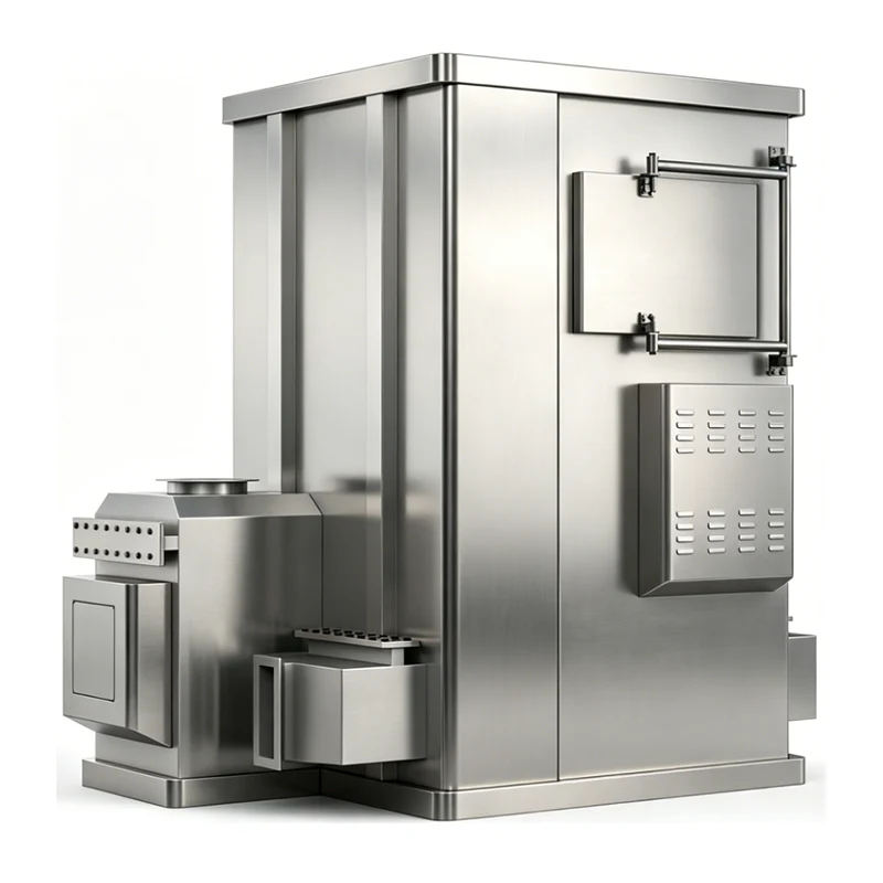
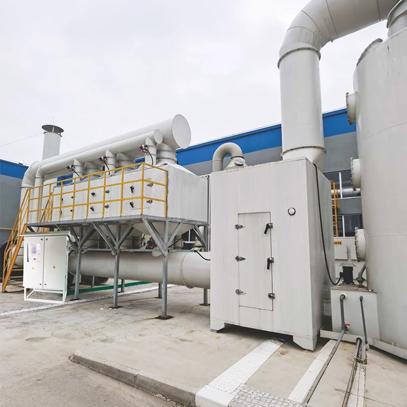
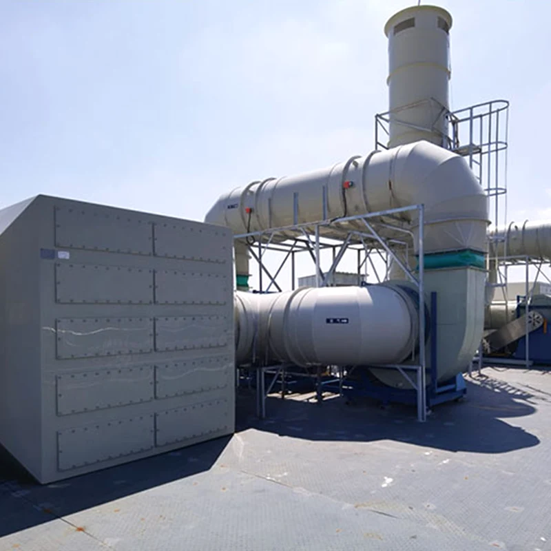
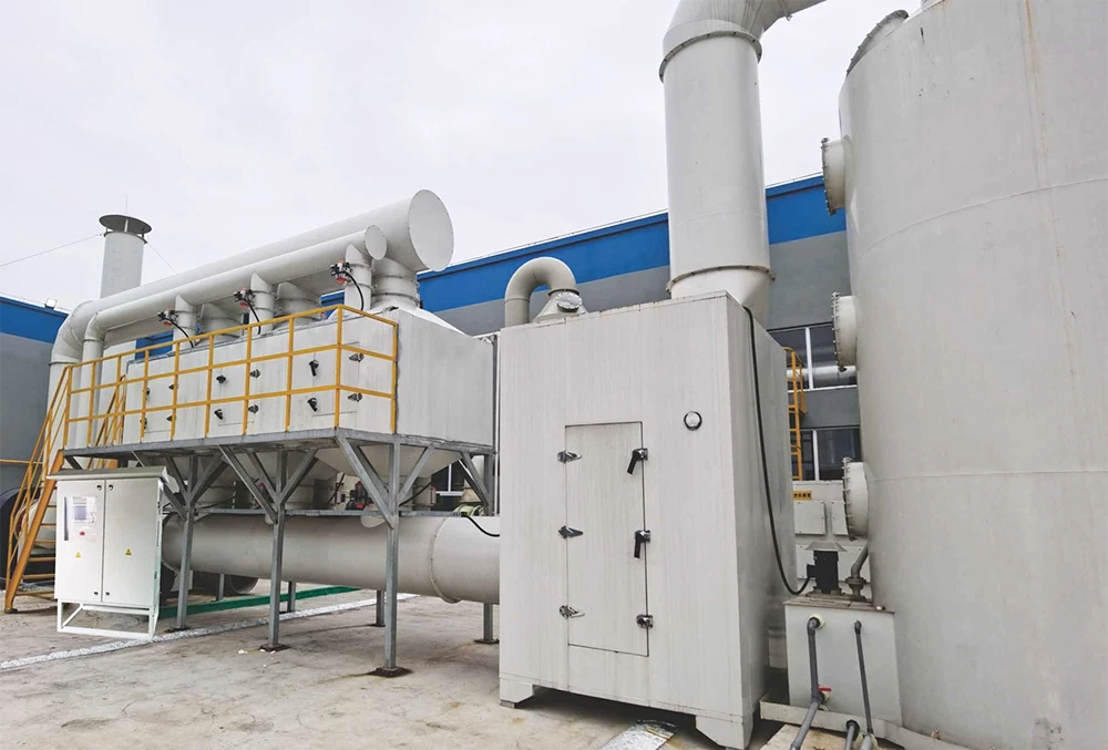
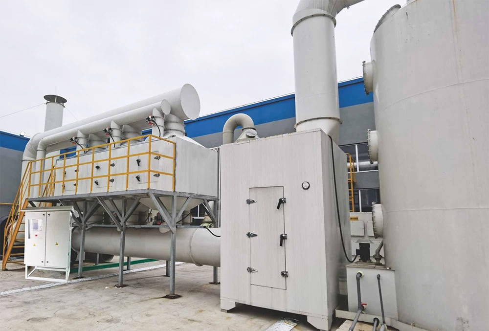
Important red flags include extremely dilute high-airflow exhaust, long idle periods, sticky aerosol, polymerizing material, particulate, and sulfur- or halogen-containing compounds that may create corrosive products after oxidation. Pretreatment, corrosion control or a downstream scrubber may be required. DeFa's regenerative thermal oxidizer equipment page shows the available equipment concept; the final chamber arrangement, materials and operating envelope should be specified from the actual exhaust analysis.
When activated carbon is the stronger candidate
Activated carbon is often easier to justify for a lower mass load, intermittent vent or final polishing stage. The gas should be compatible with the selected carbon, and the facility needs enough operating discipline to detect breakthrough before the outlet limit is exceeded.
Carbon adsorption deserves closer evaluation when:
- The VOC load is low enough that the predicted replacement or regeneration interval is practical.
- Emissions occur intermittently and an oxidizer would spend much of its time warming up or operating at low load.
- The gas can be cooled, dried or prefiltered to protect the adsorption bed.
- The target compounds have suitable adsorption behavior and will not create an unacceptable reaction or hot-spot risk.
- A polishing stage is needed after condensation, scrubbing or another primary control device.
Carbon is not a fit-and-forget filter. EPA recommends monitoring outlet VOC concentration, bed temperature, inlet gas temperature, gas flow, inlet concentration, pressure differential and inlet moisture. High humidity and elevated temperature can reduce useful capacity, while mixed solvents can compete for adsorption sites and break through at different times. A supplier's equilibrium capacity should not be used as the changeout basis without applying working-capacity and safety factors.
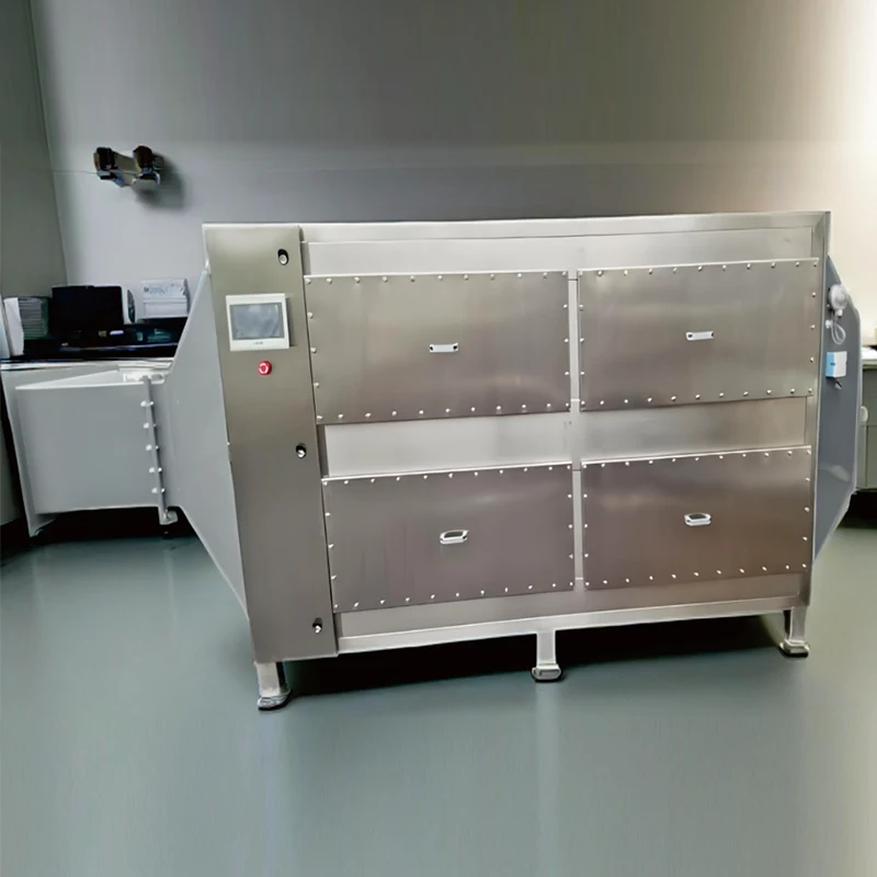
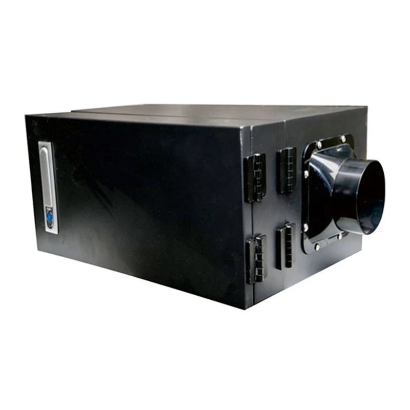
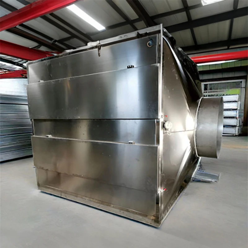
DeFa's activated carbon box equipment is a modular option for compatible VOC and odor duties. Confirm carbon type, media mass, bed depth, gas residence time, pressure drop, prefiltration, temperature monitoring and changeout access in the quotation.
Compare lifecycle cost, not purchase price
RTO and activated carbon move costs into different categories. A carbon box can have a simpler initial equipment package, but recurring media cost rises with captured VOC mass. An RTO typically requires more capital and controls, while its operating economics improve when heat recovery and the VOC heat input reduce auxiliary fuel demand.
| Cost area | RTO questions | Activated carbon questions |
|---|---|---|
| Energy | What is the fuel demand at minimum, normal and peak VOC loading? What fan power is required at clean and dirty pressure drop? | What fan power is required through the bed and prefilters? Does regeneration require steam, nitrogen, vacuum or cooling? |
| Consumables | Fuel, filters, seals and periodic high-temperature components | Carbon, prefilters, sampling and disposal or reactivation |
| Labor and downtime | Burner, valve, ceramic media, refractory, instrumentation and heat-balance inspections | Breakthrough testing, carbon changeout, vessel entry controls and waste documentation |
| Secondary treatment | Possible acid-gas scrubbing, quench or condensate management | Spent carbon, regeneration off-gas, condensate or recovered-solvent handling |
| Production risk | What happens to production during an RTO trip or maintenance outage? | What happens if breakthrough occurs sooner than the planned changeout? |
Model at least three operating cases: minimum load, normal production and credible peak load. Then annualize fuel, electricity, carbon, waste, labor and planned downtime over the same evaluation period. A single equipment price or claimed removal percentage cannot answer which option costs less at the site.
Compare the failure modes before choosing
RTO operating risks
The safety design must address flammable mixtures, ignition sources, purge cycles, burner management, valve sequencing, high temperature, pressure, emergency shutdown and abnormal concentration peaks. The inlet operating envelope should be defined from compound-specific flammability data and a qualified process-safety review. Outlet VOC and combustion-chamber temperature are primary performance indicators identified by EPA, with gas flow, carbon monoxide, oxygen and auxiliary-fuel pressure providing additional operating evidence.
Activated carbon operating risks
Adsorption releases heat. Certain compounds or high vapor loads can create hot spots in a carbon bed, so composition review, temperature monitoring and fire-prevention measures belong in the design. The EPA chemical safety alert on carbon adsorption systems specifically warns that some vapor mixtures can produce enough heat to create a fire hazard and recommends qualified design, evaluation of vapor composition, inspection and appropriate prevention and mitigation systems.
Early breakthrough is the other major failure mode. It can result from underestimated peak loading, humidity, elevated temperature, channeling, particulate or oil contamination, a change in solvent mixture or the use of an unsuitable carbon. An outlet measurement or compound-specific breakthrough indicator is more defensible than replacing media on calendar time alone.
Sometimes the answer is neither system by itself
A large, dilute exhaust stream can be uneconomic for a full-flow oxidizer and too large for frequent disposable-carbon replacement. Before increasing equipment size, review source capture, enclosure leakage and whether clean dilution air can be separated from the VOC-rich source.
Common combined approaches include:
- Concentrator plus RTO: a suitable adsorbent rotor captures VOCs from a large dilute stream and sends a smaller desorption stream to the oxidizer.
- Pretreatment plus RTO: filtration, mist collection, cooling or scrubbing protects the ceramic media and downstream components.
- Primary control plus carbon polishing: a low-load carbon stage captures residual VOCs after condensation, scrubbing or another main device.
- Source segregation: high-concentration vents go to oxidation or recovery while low-load intermittent sources use a separate adsorption stage.
Hybrid equipment should be designed as one treatment train. A concentrator's desorption temperature and ratio affect the oxidizer; a prefilter's pressure drop affects capture; and a polishing carbon bed still requires a breakthrough plan.
A practical RTO versus activated carbon selection workflow
- Confirm the compliance target. Record the pollutant definition, outlet limit, test method, averaging period and any operating-parameter requirements.
- Measure the complete load profile. Capture minimum, normal and peak airflow and VOC concentration during every important production state.
- Identify the compounds and co-pollutants. Review adsorption compatibility, oxidation byproducts, corrosion, fouling and fire hazards.
- Reduce unnecessary airflow. Improve enclosure and source segregation before sizing a larger control device.
- Prepare two mass and energy balances. For RTO, calculate heat demand across the operating range. For carbon, estimate compound-specific working capacity and changeout or regeneration frequency.
- Price the same lifecycle. Include utilities, consumables, waste, labor, testing, planned maintenance and production downtime.
- Define acceptance and monitoring. Agree on inlet conditions, guaranteed outlet basis, sampling points, alarms, maintenance triggers and response to abnormal operation.
Request an RTO and carbon comparison for your exhaust stream
DeFa Environmental Equipment supplies industrial waste gas treatment equipment, including RTO and activated carbon systems. Send the airflow range, VOC compound list, concentration profile, temperature, humidity, operating schedule and required outlet limit. The engineering team can use the same design basis to compare a destruction, adsorption or combined treatment concept.
Frequently asked questions
Is RTO always better for high VOC concentration?
No. Higher VOC heat input can improve an oxidizer's energy balance, but compound chemistry, flammability, corrosion, peak loading and recovery value may change the decision. Condensation or solvent recovery may be preferable for some concentrated streams.
Is activated carbon suitable for continuous industrial VOC treatment?
It can be, if the media capacity, bed configuration, regeneration or replacement plan and monitoring system match the continuous mass load. A disposable carbon box that is economical for an intermittent vent may require impractically frequent changeout on a continuous high-load source.
Which system has the lower operating cost?
The answer depends on annual VOC mass, airflow, operating hours, RTO heat balance, carbon working capacity, pressure drop, utilities, maintenance and waste cost. Compare annualized costs under the same minimum, normal and peak production cases.
Can activated carbon and RTO be used together?
Yes. Adsorption or a concentrator can transfer VOCs from a large dilute stream into a smaller desorption stream for oxidation. Carbon can also serve as a polishing stage. Media compatibility, desorption conditions, safety controls and monitoring must be designed with the downstream oxidizer.