Prepared by the DeFa Engineering Team
Quick answer
An RTO treats industrial VOC exhaust in three repeating stages. First, a hot ceramic bed preheats the incoming gas. Second, the gas enters a combustion chamber where sufficient temperature, residence time and mixing allow compatible organic compounds to oxidize. Third, the treated hot gas passes through another ceramic bed and transfers much of its heat to that media before leaving the system. Switching valves periodically reverse the airflow so the beds alternate between releasing and storing heat.
The RTO working principle is straightforward, but reliable operation depends on the real exhaust composition, VOC mass loading, airflow, particulate or mist content, temperature range, safety controls and emission limit. For technology selection beyond RTO, see the industrial VOC treatment guide.
The RTO working principle: oxidation plus regenerative heat recovery
A thermal oxidizer is a combustion device used to control volatile organic compounds, carbon monoxide and selected volatile hazardous air pollutants. The U.S. EPA thermal oxidizer guidance identifies three central design factors: a temperature high enough for the target organic constituents, enough residence time for the reaction, and adequate turbulence or mixing between the waste gas and combustion air.
The word regenerative refers to the heat-recovery method. Instead of discharging all the heat after oxidation, an RTO passes the hot treated gas through a fixed ceramic bed. The ceramic media absorbs heat. After the airflow switches direction, that stored heat preheats the next portion of incoming exhaust. EPA distinguishes this alternating-bed arrangement from recuperative oxidizers, which use a conventional non-contact heat exchanger.
The ceramic media does not remove the VOC by itself. Its job is to move heat from the treated outlet side to the untreated inlet side. VOC destruction occurs in the heated reaction zone when the required operating conditions are maintained.
How the RTO operating cycle works
- Collection and inlet control. A fan draws captured process exhaust through ductwork and any required pretreatment. Dampers, isolation devices and safety instruments control entry into the RTO.
- Preheating in the inlet ceramic bed. The cooler VOC-laden gas passes through ceramic media that retained heat during the previous cycle. Its temperature rises before it reaches the combustion chamber.
- Thermal oxidation. The preheated gas enters the chamber. A burner supplies the additional heat required during startup or low-load operation. Temperature, time and mixing must match the compounds and agreed destruction duty.
- Heat storage on the outlet side. The treated gas enters a cooler ceramic bed. Heat transfers from the gas to the media, lowering the outlet temperature while preparing that bed for the next inlet cycle.
- Valve switching and purge. The valves change position so the hot outlet bed becomes the next inlet bed. In a multi-chamber configuration, a purge step can move residual untreated gas out of the chamber before it becomes an outlet path.
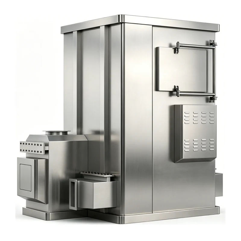
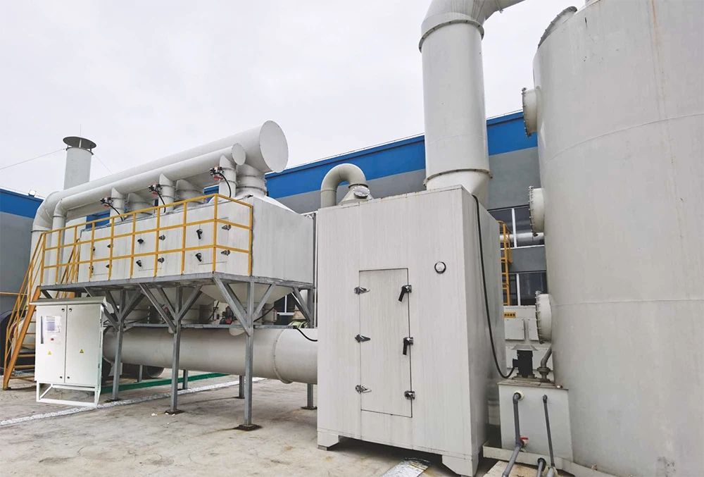
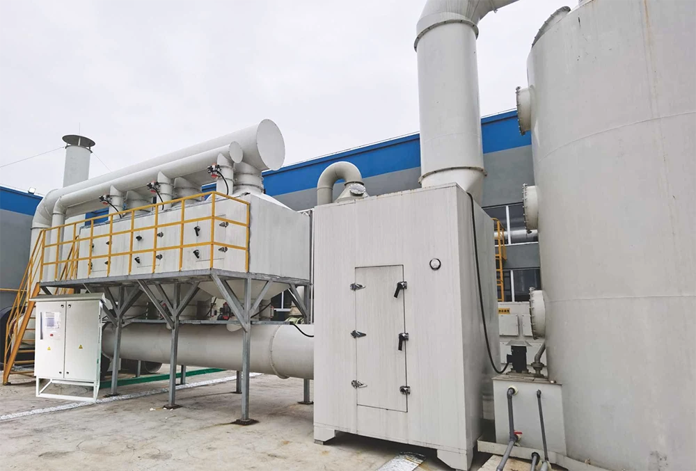
This sequence repeats continuously. DeFa's regenerative thermal oxidizer equipment description uses a multi-chamber arrangement with ceramic heat-storage sections, switching valves and a dedicated purge stage. The final chamber count and valve sequence should be selected for the required airflow, removal duty, pressure behavior and operating continuity.
Core components and what each one does
| Component | Function | What to check |
|---|---|---|
| Capture duct and induced-draft fan | Moves process exhaust from the source through the treatment system | Airflow, fan current, leakage, pressure and source capture |
| Inlet isolation and safety devices | Control whether exhaust can enter under normal or abnormal conditions | Position feedback, interlocks, alarms and fail-safe action |
| Switching valves | Reverse the direction of flow through the ceramic beds | Timing, seal condition, leakage and actuator response |
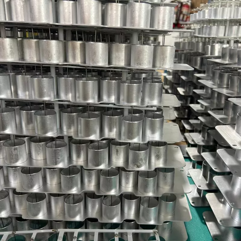
| Ceramic media beds | Store heat from treated gas and release it to incoming gas | Temperature profile, pressure drop, deposits and bed condition |
| Combustion chamber and burner | Provide the reaction zone and supplemental heat | Chamber temperature, fuel pressure, flame safety and refractory condition |
| Purge system | Reduces untreated gas carryover during valve switching | Purge flow, timing and valve coordination |
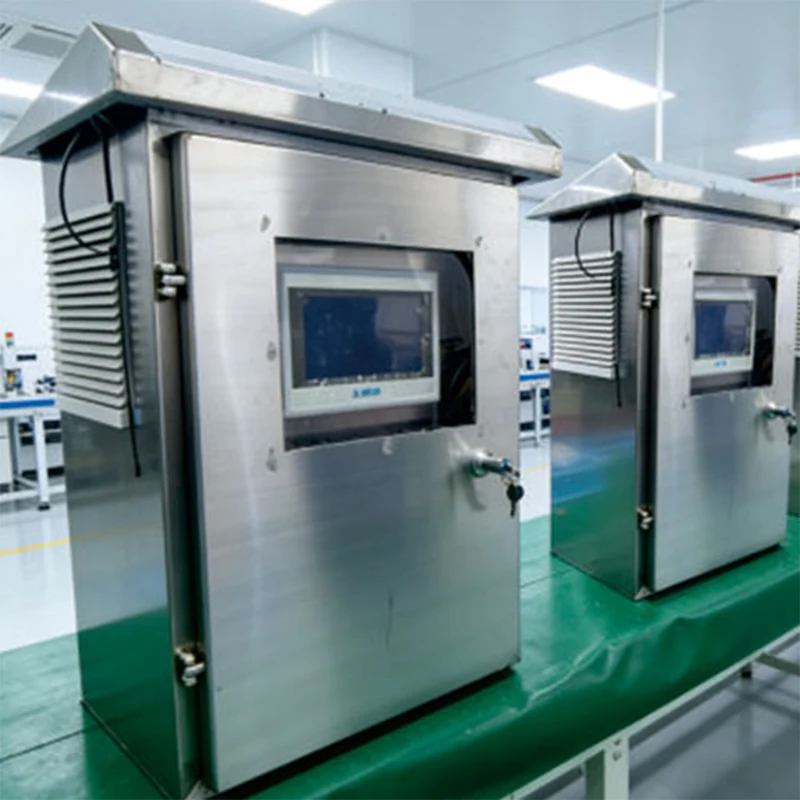
| Controls and instrumentation | Sequence startup, operation, shutdown and protective responses | Sensor calibration, alarm history, trends and data retention |
| Stack and sampling provisions | Discharge treated gas and support performance testing | Sampling access, flow conditions and required monitoring points |
Which RTO operating parameters matter most?
EPA identifies outlet VOC concentration and combustion-chamber temperature as primary performance indicators for VOC control. Other useful indicators include outlet carbon monoxide, gas flow rate, fan current, outlet carbon dioxide and oxygen, and auxiliary-fuel pressure. The applicable permit may require a specific subset, averaging period, alarm response or recordkeeping method.
A useful operating dashboard should also show the temperature distribution across the ceramic beds, pressure drop, switching-valve status, burner state and inlet VOC or flammability condition where required by the safety design. One reading cannot prove that the complete system is healthy. For example, a normal chamber temperature does not reveal poor source capture, a leaking valve or a blocked section of ceramic media.
Why VOC mass loading changes RTO fuel consumption
RTO economics depend on both airflow and the chemical energy entering with the VOCs. A large flow of very dilute air requires more gas to be heated, while providing less heat from VOC oxidation. A higher compatible VOC mass load can reduce burner demand, but the system still has to remain inside its designed thermal and flammability envelope.
VOC mass loading (kg/h) = airflow (m³/h) × concentration (mg/m³) ÷ 1,000,000
This calculation is only a first step. A real heat balance also needs inlet temperature, individual compounds and heating values, air leakage, ceramic performance, operating schedule, startup frequency and heat losses. If the stream is extremely dilute, compare source segregation or concentration before committing to a full-flow RTO. The focused RTO versus activated carbon comparison explains how mass loading changes the technology shortlist.
Common RTO operating problems and first checks
| Symptom | Possible causes | First checks |
|---|---|---|
| Fuel use rises | Lower VOC load, excess dilution air, air leakage, heat-recovery deterioration or longer idle operation | Compare airflow, inlet VOC load, temperature balance and production schedule with the design basis |
| Pressure drop increases | Dust, oil, sticky condensables or damaged media restricting the bed | Inspect pretreatment, pressure trends and media condition |
| Outlet VOC increases during switching | Valve leakage, incorrect timing or inadequate purge | Review valve position feedback, sealing, purge flow and cycle trends |
| Uneven bed temperatures | Flow maldistribution, deposits, media damage or valve problems | Compare temperature zones, pressure data and valve sequence |
| Corrosion or deposits appear | Unexpected compounds, acid-forming products, condensation or inadequate pretreatment | Recheck gas speciation, dew point, materials and downstream treatment needs |
Do not adjust safety limits or bypass interlocks as a troubleshooting shortcut. Changes involving burners, flammable gases, purge logic or emergency shutdowns require qualified personnel and the site's approved management-of-change procedure.
Information required before specifying an RTO
- Minimum, normal and maximum airflow
- VOC concentration profile, including startup, cleaning and batch peaks
- Individual VOC compounds, oxygen level and flammability information
- Temperature, humidity, pressure and expected operating schedule
- Dust, oil mist, acid mist, aerosols and condensable material
- Required outlet limit, removal basis, test method and averaging period
- Available fuel and electricity, space, noise limit and maintenance access
- Expansion plans, redundancy needs and production response to an RTO trip
Need an RTO concept based on your exhaust data?
DeFa Environmental Equipment supplies industrial waste gas treatment equipment, including regenerative thermal oxidizer systems and supporting pretreatment. Send the airflow range, compound list, concentration profile, temperature, operating hours and required outlet limit for an engineering review.