How Can High-Viscosity Oil Fume Purification Equipment Improve Industrial Air Quality and Production Efficiency
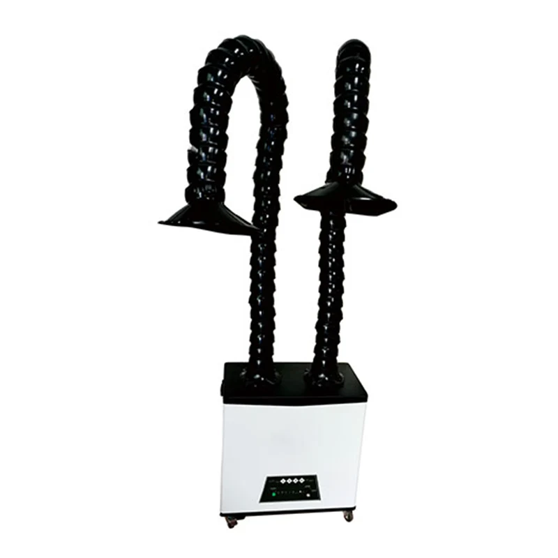
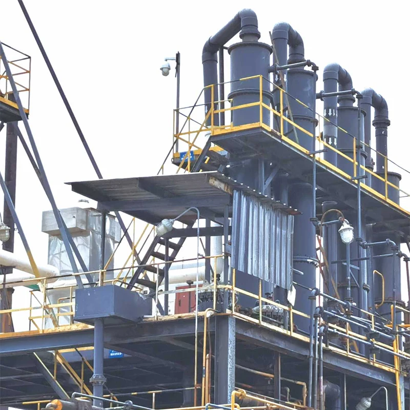
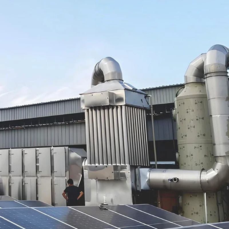
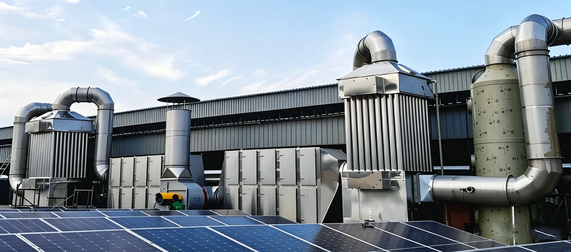
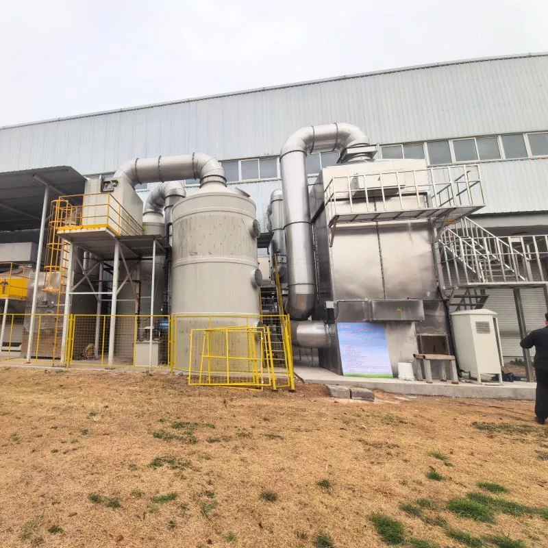
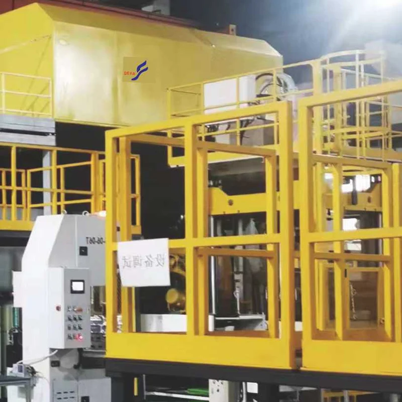
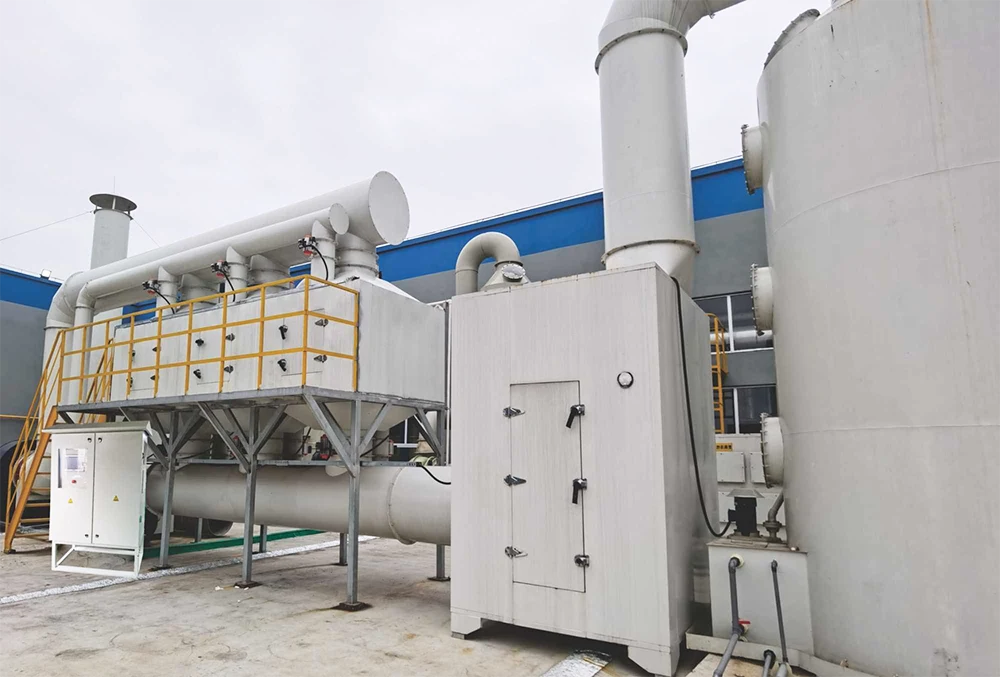
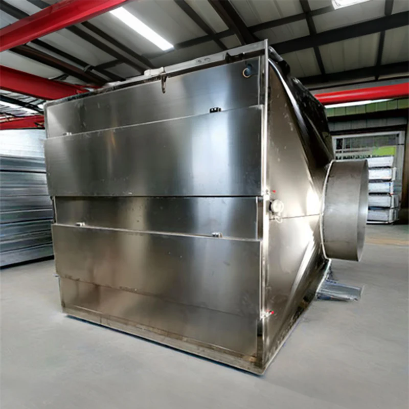
DeFa High-Viscosity Oil Fume Purification Equipment helps manufacturers control sticky oil mist generated by quenching, cold heading, wire drawing, and heavy-duty machining. Its staged purification design supports cleaner workshops, reduced oil accumulation, and more reliable industrial exhaust management.
High-viscosity oil mist is a persistent challenge in metalworking and industrial manufacturing. Unlike ordinary airborne particles, sticky oil droplets can accumulate on duct walls, clog filter media, and reduce ventilation performance. Selecting the right purification equipment requires an understanding of oil characteristics, mist concentration, airflow, operating temperature, and maintenance requirements. This guide explains how mechanical pre-separation, coalescing filtration, and optional electrostatic capture work together to control oil mist. It also examines typical applications, equipment selection criteria, installation practices, and preventive maintenance. By evaluating these factors before purchasing, manufacturers can develop a practical purification strategy that improves workplace air quality and supports long-term operational reliability.
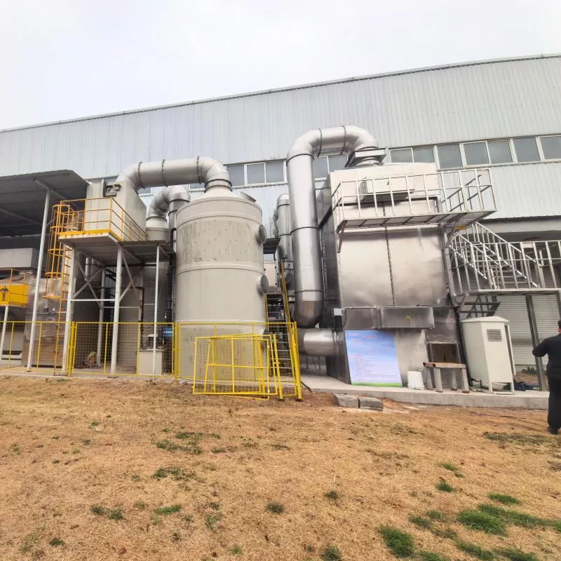
Table of Contents
- 1. Why Is High-Viscosity Oil Mist Difficult to Control?
- 2. How Does High-Viscosity Oil Fume Purification Equipment Work?
- 3. What Features Should Industrial Buyers Evaluate?
- 4. What Technical Parameters Matter Most?
- 5. Which Industries Benefit from This Equipment?
- 6. How Should You Select the Right Purification System?
- 7. How Can Installation and Maintenance Improve Performance?
- 8. Frequently Asked Questions
- 9. Conclusion
1. Why Is High-Viscosity Oil Mist Difficult to Control?
Industrial oil mist is produced when lubricants, quenching oils, and cutting fluids are exposed to mechanical forces, elevated temperatures, or high-speed processing. The resulting airborne droplets can combine with fine metal particles and other contaminants, creating a complex exhaust stream.
High-viscosity oil mist presents several specific challenges:
- Sticky deposits: Oil droplets adhere to ventilation ducts, filter surfaces, and equipment housings.
- Filter blockage: Accumulated oil can restrict airflow and increase system resistance.
- Maintenance demands: Deposits on fans and internal components may require frequent cleaning.
- Uneven capture: Poorly designed extraction systems may allow contaminants to escape into the workshop.
- Potential safety concerns: Certain oil mists and mixed metal dusts require specialized risk assessment and appropriately designed treatment systems.
Conventional filtration may struggle when sticky droplets rapidly saturate the filter media. A purpose-designed purification system addresses this problem by separating larger contaminants first and allowing collected oil to drain rather than remain trapped in the filtration layer.
2. How Does High-Viscosity Oil Fume Purification Equipment Work?
A staged treatment process can improve contaminant removal while reducing the burden on individual components. DeFa's equipment is designed around mechanical pre-separation and coalescing filtration, with electrostatic capture available as an additional treatment stage where appropriate.
Stage 1: Mechanical Pre-Separation
The contaminated airflow enters a separation chamber, where baffles or cyclone-based mechanisms use inertia and centrifugal forces to remove larger oil droplets and solid particles. Separated material moves toward a collection tank, reducing the contaminant load reaching downstream components.
Stage 2: Coalescing Filtration
The air then passes through specialized coalescing media. Fine droplets collide with the fibers, combine into larger droplets, and drain under gravity. This process helps prevent sticky oil from accumulating excessively within the filter structure.
Stage 3: Optional Electrostatic Capture
When the application requires additional fine-mist removal, an electrostatic stage can capture residual airborne oil droplets. A high-voltage electric field charges particles and attracts them to collection plates, where the accumulated oil can drain away.
Electrostatic treatment is not suitable for every exhaust stream. Oil mist containing combustible aluminum or magnesium dust requires particular caution because of the ignition risks associated with high-voltage equipment. The treatment configuration must therefore be selected after reviewing the actual contaminants and conducting a process-specific safety assessment.
Stage 4: Oil Collection and Drainage
Separated oil collects in a designated tank and is discharged through a manual or automatic drain. Depending on its condition and applicable regulations, recovered process oil may be filtered and reused. Contaminated, degraded, or otherwise unsuitable oil should be handled according to the relevant waste-management requirements.
3. What Features Should Industrial Buyers Evaluate?
Reliable purification depends on more than the filter itself. Equipment design should address the physical behavior of sticky oil, the operating environment, and the practical needs of maintenance teams.
Oversized Pre-Separation and Oil Collection
A properly sized separation chamber and collection tank help accommodate heavier oil loading. Suitable internal spacing also allows separated oil to drain more effectively, reducing the risk of persistent deposits.
Serviceable Coalescing Modules
Accessible filter modules make inspection, cleaning, and replacement more convenient. Depending on the selected media, cleaning procedures should follow the manufacturer's recommendations to avoid damaging the filtration structure.
Intelligent Electrical Protection
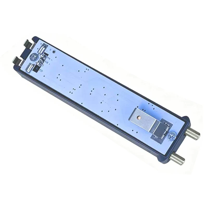
Where an electrostatic stage is installed, appropriate power control and protective functions can help manage electrical faults and unstable operating conditions. Interlocks, alarms, and monitoring options should match the production line's safety requirements.
Drain-Friendly Ductwork
Duct layout is an important part of purification performance. Properly engineered slopes, drainage points, and airflow distribution help minimize oil accumulation and make the system easier to maintain.
For broader industrial air-treatment requirements, buyers can also review DeFa's industrial dust removal equipment and waste gas treatment equipment to understand the available treatment categories.
4. What Technical Parameters Matter Most?
Before requesting a quotation, buyers should establish the operating conditions and performance requirements of their applications. The following figures summarize the published configuration ranges for DeFa High-Viscosity Oil Fume Purification Equipment. Final values depend on the selected model and project conditions.
| Parameter | Published Range or Requirement | Why It Matters |
|---|---|---|
| Airflow per unit | 500–20,000 m³/h | Determines the volume of contaminated air the system can handle. |
| Recommended inlet oil mist concentration | ≤500 mg/m³ | Higher concentrations may require additional pre-separation or pre-cooling. |
| Mechanical and coalescing removal efficiency | ≥95% | Indicates the published removal performance of the combined stages under specified conditions. |
| Removal efficiency with electrostatic capture | ≥99% | Provides an additional fine-mist treatment option for suitable applications. |
| Outlet concentration | Down to ≤10 mg/m³ | Supports emissions planning; actual results depend on inlet conditions and configuration. |
| Pressure drop | 300–800 Pa for pre-separation and coalescing; up to 1,000 Pa with electrostatic capture | Influences fan selection and energy consumption. |
| Standard inlet temperature | ≤80°C | Higher temperatures may require a suitable pre-cooling section. |
| Fan power | 0.55–15 kW | Must be matched to airflow, duct resistance, and the selected configuration. |
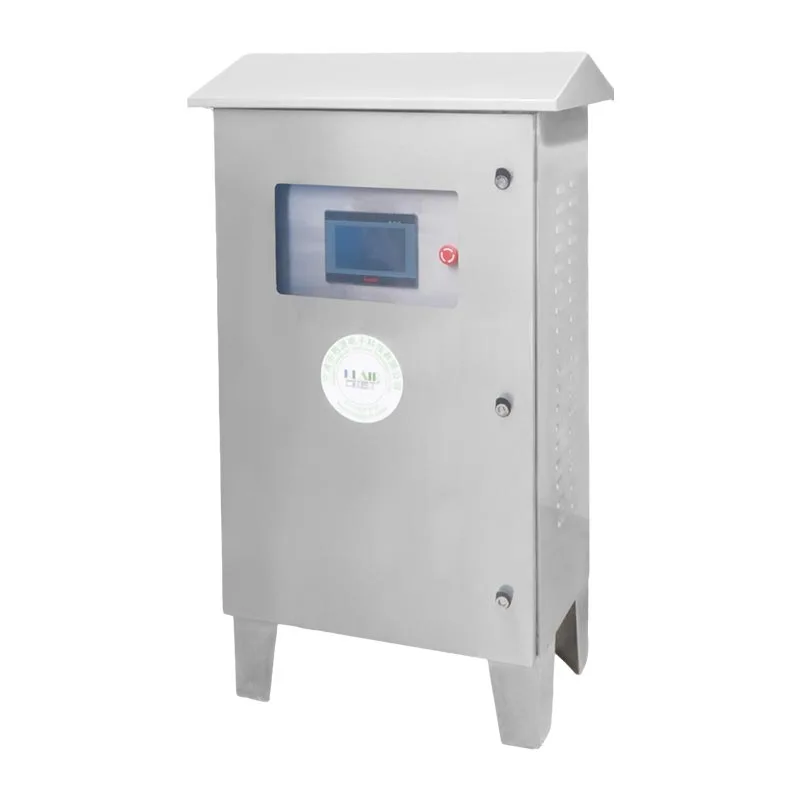
| Control options | Manual operation; optional PLC interlock and monitoring | Supports integration with production equipment and maintenance procedures. |
Note: These are published product specifications, not a guarantee that every configuration will achieve the same results. Confirm the model-specific data, test conditions, and applicable emission limits with the supplier before purchase.
5. Which Industries Benefit from This Equipment?
High-viscosity oil fume purification is particularly relevant to manufacturing processes that generate persistent oil mist or combine airborne oil with metalworking residues.
Heat Treatment and Quenching
When hot workpieces enter quenching oil, the resulting emissions may contain oil mist, fumes, and solid residues. A suitable extraction hood and, where necessary, pre-cooling section help prepare the exhaust for treatment.
Cold Heading and Cold Extrusion
Fast-forming operations use lubricants to reduce friction and tool wear. Local extraction combined with effective pre-separation can help control oil mist and prevent metal chips from reaching sensitive filtration components.
Wire Drawing and Tube Processing
Lubricated drawing processes may release oil mist at multiple production points. A centralized system can serve several machines when the duct network, airflow balance, and maintenance access are properly engineered.
Heavy-Duty CNC Machining
Turning, milling, and deep-hole drilling can produce significant quantities of cutting-fluid mist. Depending on machine layout and contaminant loading, manufacturers may choose individual machine-mounted units or a centralized purification system.
For facilities with several production processes, the exhaust should be assessed as a complete system rather than selecting equipment solely by machine count. Different contaminants may require separate collection networks or additional treatment stages.
6. How Should You Select the Right Purification System?
The most suitable system is the one that matches the real operating conditions, not necessarily the unit with the highest nominal airflow or removal-efficiency figure.
- Identify the oil type. Document the lubricant, quenching oil, or cutting fluid used and review its safety data sheet.
- Measure the exhaust conditions. Estimate or measure airflow, oil mist concentration, temperature, and the presence of metal particles.
- Define the capture points. Determine whether the equipment should serve one machine, several machines, or an entire production area.
- Set the performance target. Specify required outlet concentrations, local emission limits, and any additional VOC treatment needs.
- Review safety compatibility. Evaluate combustible dust, flammable vapors, grounding, electrical protection, and explosion-proof requirements.
- Compare lifecycle costs. Consider energy use, filter cleaning, spare parts, labor, downtime, and oil collection arrangements.
- Confirm commissioning support. Establish how airflow, capture effectiveness, pressure drop, and outlet performance will be verified.
A well-prepared technical brief allows the supplier to recommend a more appropriate configuration and reduces the likelihood of under-sized fans, inadequate extraction, or unnecessarily complicated treatment stages.
7. How Can Installation and Maintenance Improve Performance?
Even well-designed purification equipment can perform poorly when extraction hoods, ducts, or maintenance procedures are inadequate. A planned installation and inspection schedule helps preserve airflow and treatment effectiveness.
Installation Recommendations
- Position the capture hood as close as practical to the oil mist source.
- Minimize unnecessary duct length and avoid layouts that encourage oil pooling.
- Provide accessible drainage points and sufficient space for filter removal.
- Verify fan capacity against actual system resistance and required capture airflow.
- Use appropriate grounding, electrical protection, and production interlocks.
- Commission the system under representative operating conditions and record baseline readings.
Suggested Preventive Maintenance Schedule
| Component | Suggested Inspection Interval | Maintenance Action |
|---|---|---|
| Oil collection tank | Daily or each shift | Check oil level and confirm that drainage is unobstructed. |
| Pre-separation chamber | Weekly | Inspect for sticky deposits and accumulated metal particles. |
| Coalescing filter module | Every 1–2 months | Inspect and clean or replace according to loading and manufacturer guidance. |
| Electrostatic collection plates | Every 1–2 months, if installed | Isolate electrical power, safely discharge the system, and clean as instructed. |
| Power supply and insulators | Quarterly, if installed | Inspect insulation condition and verify electrical performance. |
| Fan and ductwork | Quarterly to every six months | Check deposits, vibration, drainage, leakage, and airflow performance. |
These intervals are starting points rather than universal requirements. Heavy oil loading may demand more frequent service. Always isolate and lock out equipment before maintenance, and follow the manufacturer's electrical and chemical-handling instructions.
8. Frequently Asked Questions
Q1: What makes high-viscosity oil fume purification equipment different from a standard oil mist purifier?
High-viscosity oil mist tends to adhere to internal surfaces and saturate conventional filter media. Purpose-designed systems use staged pre-separation, drainage-oriented coalescing filtration, and optional electrostatic capture to manage sticky droplets more effectively.
Q2: Can electrostatic purification be used with every type of industrial oil mist?
No. The suitability of electrostatic capture depends on the contaminants and the process risk assessment. In particular, oil mist containing combustible aluminum or magnesium dust presents a potential ignition hazard in a high-voltage field. The treatment method must be selected for the specific application.
Q3: Can collected oil be reused?
Potentially. Oil that remains suitable for the production process may be filtered to remove solid impurities and returned to service. Oxidized, degraded, or heavily contaminated oil should not be reused without an appropriate technical assessment.
Q4: What causes purification efficiency to decrease?
Common causes include saturated coalescing media, deposits on electrostatic plates, obstructed drainage, fan contamination, duct leakage, and insufficient extraction airflow. Routine inspections and performance measurements help identify the underlying problem.
Q5: Can the equipment meet local environmental emission requirements?
The published configuration can achieve different removal efficiencies depending on the selected treatment stages and operating conditions. Compliance must be verified against the applicable local requirements using suitable measurement methods. Additional treatment may be necessary when the exhaust contains VOCs or other pollutants beyond the system's intended scope.
Q6: What information should buyers provide when requesting a quotation?
Provide the application, oil type, estimated airflow, inlet temperature, contaminant concentration, operating hours, available installation space, dust hazards, and target outlet limits. This information helps the supplier evaluate equipment capacity and treatment compatibility.
9. Conclusion
High-viscosity oil mist requires a purification strategy that accounts for sticky droplets, contaminant loading, drainage, airflow, and maintenance access. Mechanical pre-separation and coalescing filtration provide the foundation for controlling oil mist, while electrostatic capture can offer additional treatment when the application is suitable. Careful equipment selection, safe installation, and routine maintenance are essential to achieving dependable performance. For manufacturers comparing industrial purification solutions, the best approach is to evaluate the entire exhaust system against real production conditions and measurable environmental targets.
DeFa provides industrial air purification and oil mist treatment solutions for applications including quenching, cold heading, wire drawing, and heavy-duty machining. If you are planning a new installation or upgrading an existing exhaust system, explore DeFa High-Viscosity Oil Fume Purification Equipment and contact us with your process details to discuss a suitable configuration, technical requirements, and a customized quotation.
Related News
- How Can a Rectangular Air Volume Control Damper Improve HVAC Efficiency and Airflow Precision
- Industrial VOC Removal: How Pretreatment Protects Activated Carbon, Zeolite Rotors and RTO Systems
- How Can an Acidic Waste Gas Treatment System Improve Industrial Safety and Emission Control
- How Can a Quenching Furnace Oil Fume Purification System Improve Industrial Air Quality and Production Efficiency
- Can a Wet Scrubber Remove VOCs? A Practical Selection and Troubleshooting Guide
- How Can an Intelligent Purification Power Supply and Control System Assembly Transform Industrial Air Pollution Control
Leave me a message