Prepared by the DeFa Engineering Team
Quick answer
Activated carbon removes VOCs by transferring molecules from the exhaust gas onto the carbon surface. The media does not have unlimited capacity. It must be replaced or regenerated before the target compounds break through the bed and exceed the outlet limit. A reliable replacement interval therefore depends on VOC mass loading, compound-specific working capacity, temperature, humidity, competing compounds, bed design, operating hours and the monitoring limit. There is no defensible universal schedule such as "replace every three months."
Carbon is often practical for lower-load or intermittent sources and polishing duties. Continuous high mass loading may make replacement expensive, in which case an oxidizer or recovery system should also be evaluated. See the RTO versus activated carbon comparison for the broader selection decision.
How activated carbon removes VOCs from exhaust gas
In adsorption, gaseous pollutants move from the air stream to the solid surface of an adsorbent. Activated carbon is widely used because its porous structure provides a large internal surface, but adsorption behavior varies by carbon type and target compound. The U.S. EPA activated carbon adsorber guidance notes that carbon, zeolites, polymers and other adsorbents may be used and that every adsorbent has a finite pollutant capacity.
A typical fixed-bed unit distributes VOC-laden gas across one or more carbon sections. The bed needs enough depth and contact time for mass transfer without creating excessive pressure drop. Prefilters may be needed when the gas contains dust, oil mist, paint overspray or sticky aerosol. Those contaminants can coat the carbon or block gas passages before the adsorption capacity is fully used.
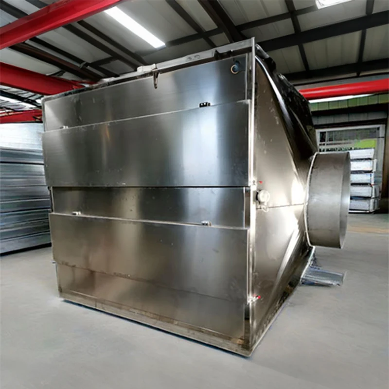
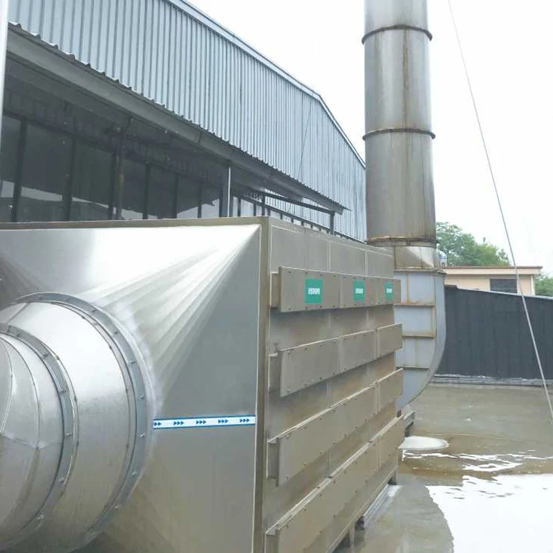
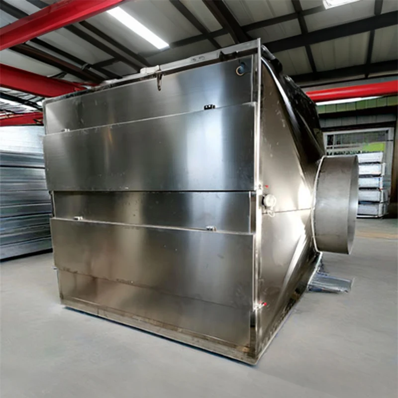
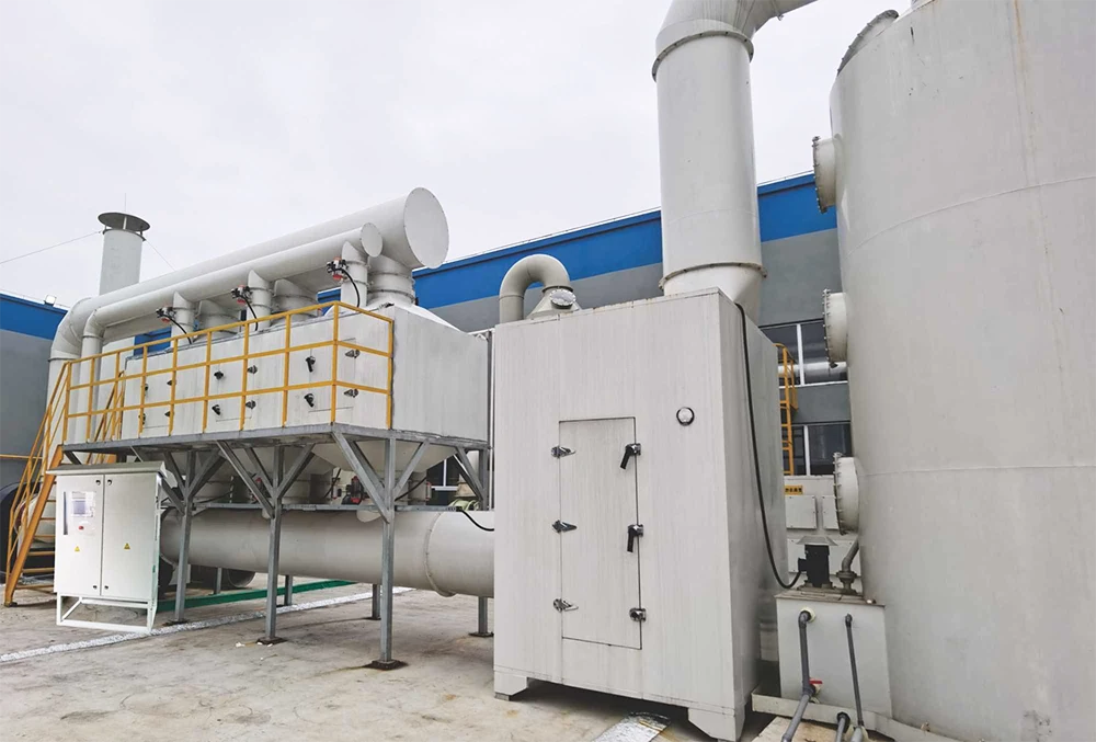
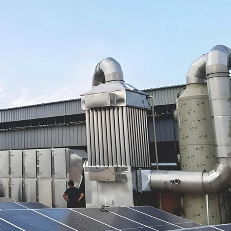
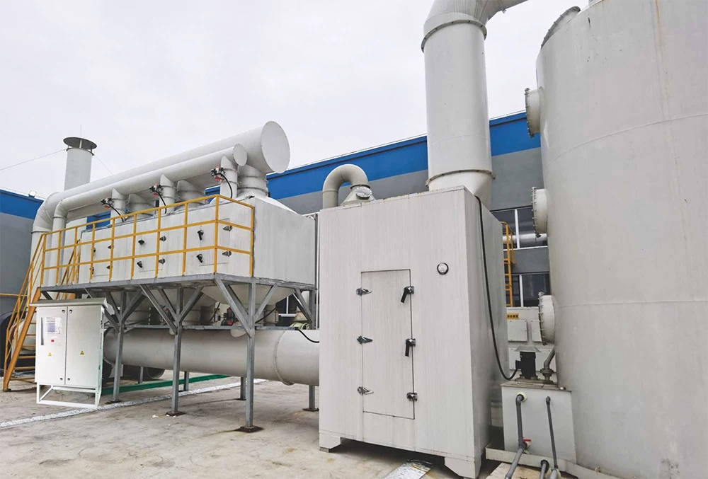
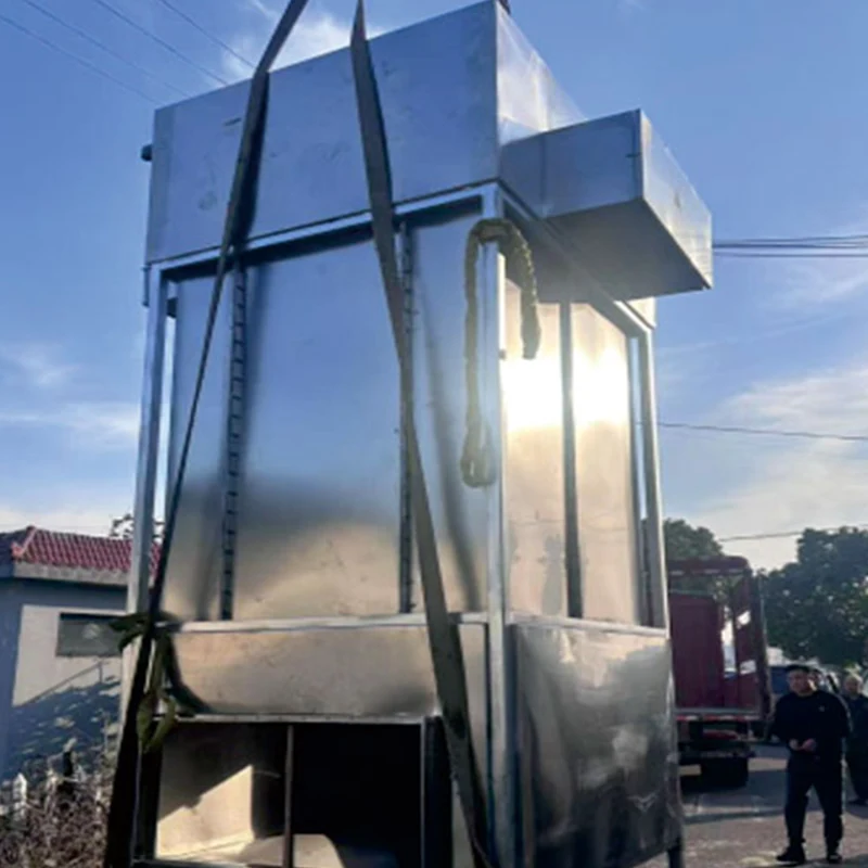
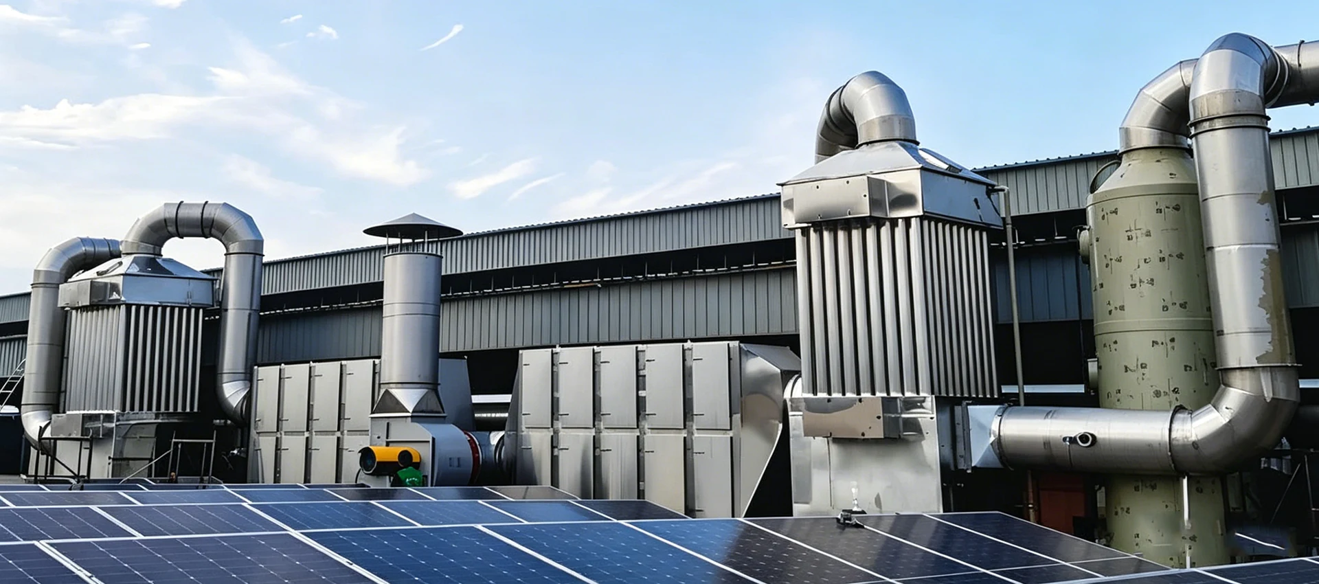
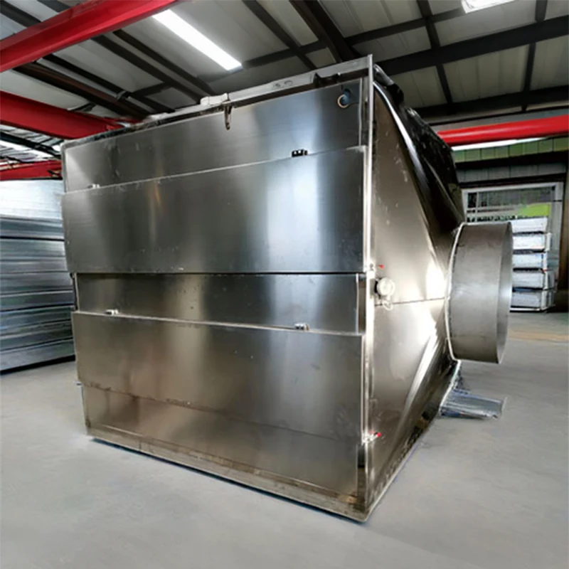
DeFa's activated carbon box equipment uses a modular duct arrangement intended for VOC and odor adsorption. A project quotation should still identify the carbon type, media mass, bed depth, gas velocity, expected pressure drop, prefiltration and changeout access for the actual stream.
Saturation capacity is not the replacement point
Three capacity terms are important:
- Saturation capacity
- The maximum pollutant mass the carbon may hold under a defined equilibrium condition.
- Breakthrough capacity
- The amount held when a significant target concentration first appears at the bed outlet.
- Working capacity
- For a regenerated system, the usable capacity between the post-regeneration heel and the selected breakthrough point.
EPA explains that breakthrough occurs before full saturation. This is why a supplier's maximum adsorption figure should not be used directly to predict the changeout date. The design needs a compound-specific usable capacity at the expected inlet concentration, temperature and humidity, plus allowances for peaks, competing VOCs, aging and the required outlet limit.
EPA gives a typical working-capacity screening range of 10 to 20 pounds of contaminant per 100 pounds of carbon, but also states that adsorption suitability must be evaluated case by case. Treat that range as background information, not a guaranteed value for a specific solvent mixture.
Estimate carbon service life from VOC mass loading
Start by converting airflow and concentration into pollutant mass. A low concentration may still consume carbon quickly when airflow and operating hours are high.
VOC inlet load (kg/h) = airflow (m³/h) × concentration (mg/m³) ÷ 1,000,000
Captured VOC (kg/day) = inlet load × operating hours × expected capture fraction
Screening service interval (days) = usable bed capacity (kg VOC) ÷ captured VOC (kg/day)
These equations are useful only when their inputs are defensible. "Usable bed capacity" is not the total carbon mass and is not the saturation figure from a generic datasheet. It must reflect the selected carbon, each important VOC, mixed-compound competition, breakthrough criterion and gas conditions. A conservative calculation should cover both normal production and short peak events.
The prediction should then be checked against outlet measurements during operation. If the measured breakthrough trend differs from the model, revise the changeout trigger and investigate the cause rather than simply shortening the calendar interval forever.
How to monitor carbon bed breakthrough
EPA identifies outlet VOC concentration as a primary performance indicator. For regenerable systems, regeneration-cycle timing, regeneration flow or vacuum and carbon-bed activity are also relevant. Other useful indicators include bed temperature, inlet temperature, gas flow, inlet concentration, pressure differential, moisture and leakage.
| Measurement | What it indicates | Possible response |
|---|---|---|
| Outlet VOC or target compound | Approach to breakthrough or an abnormal bypass path | Confirm the result, check gas distribution and apply the approved changeout trigger |
| Bed temperature | Heat release, abnormal reaction or changing adsorption load | Follow the engineered alarm and shutdown response; investigate composition and loading |
| Pressure differential | Filter loading, bed fouling, channeling or airflow restriction | Inspect prefilters, distribution and media condition |
| Inlet humidity and temperature | Conditions that can change effective adsorption capacity | Compare with the design envelope and correct upstream conditioning |
| Inlet VOC profile | Production changes, batch peaks or an underestimated mass load | Recalculate bed duty and review process changes |
The monitoring method should match the permit and the compounds that control breakthrough. A general TVOC instrument may not provide the same response to every compound. Where one hazardous or poorly adsorbed compound controls compliance, compound-specific sampling may be required.
Why activated carbon breaks through earlier than expected
| Cause | What happens | What to verify |
|---|---|---|
| Peak VOC loading was missed | A short cleaning or batch event consumes more capacity than the daily average suggests | Time-resolved inlet concentration and production records |
| Humidity is higher than specified | Water competes for sites or changes the adsorption environment | Inlet relative humidity, condensation and drying performance |
| Gas temperature is too high | Useful adsorption capacity may fall and desorption may increase | Normal and peak inlet temperature |
| Solvent mixture changed | Compounds compete, and a weakly held VOC may leave the bed first | Current SDS information and compound-specific analysis |
| Oil, dust or aerosol reaches the bed | Pores or flow passages become blocked before capacity is used | Prefilter condition, mist carryover and bed inspection |
| Air channels through the media | Part of the bed is bypassed while other areas remain underused | Media packing, seals, distribution plates and pressure profile |
| Wrong carbon or capacity assumption | The selected adsorbent does not provide the modeled working capacity | Supplier data under representative gas conditions or treatability testing |
Carbon temperature monitoring is a safety requirement
Adsorption releases heat, and some vapor mixtures can create hot spots or hazardous reactions on activated carbon. EPA's chemical safety alert for carbon adsorption systems advises facilities to assess vapor composition, use qualified design and operating supervision, inspect the system and provide appropriate fire-prevention and mitigation measures.
Temperature alarms, emergency isolation, fire detection or suppression and safe media-removal procedures must be engineered for the actual chemicals and installation. Do not assume that a carbon box is non-combustible because it has no burner. Do not open a vessel or remove hot media without the site's approved emergency and confined-space procedures.
Replace, reactivate or regenerate?
Small or low-load systems commonly replace spent carbon and send it to an approved off-site route. Larger systems may use off-site reactivation or on-site regeneration with heat, steam or vacuum. EPA notes that regeneration removes adsorbed pollutant so the media can recover adsorption ability, but the desorbed VOC still requires recovery, treatment or disposal.
Compare the options using:
- Annual captured VOC mass and predicted cycle frequency
- Carbon purchase, transport, reactivation and disposal cost
- Value and purity of any recoverable solvent
- Steam, nitrogen, vacuum, cooling and wastewater requirements
- Production downtime and safe maintenance access
- Changes in working capacity after regeneration
If the calculated media cycle is too short, reducing unnecessary airflow, separating high-load sources or selecting a destruction or recovery process may lower lifecycle cost. The RTO working-principle guide explains the alternative thermal route, while the industrial VOC treatment pillar guide compares additional technologies.
Activated carbon VOC system RFQ checklist
- Minimum, normal and maximum airflow
- Individual VOC compounds and concentration profile
- Temperature, humidity, pressure and operating schedule
- Dust, oil mist, paint aerosol, water droplets and condensables
- Required outlet limit, test method and breakthrough trigger
- Proposed carbon type, media mass, working capacity basis and safety factor
- Bed depth, residence time, clean and loaded pressure drop
- Inlet and outlet sampling points, temperature sensors and alarms
- Replacement or regeneration procedure and spent-media destination
- Fire prevention, isolation, access and emergency-response provisions
Need an activated carbon system sized to your VOC load?
DeFa Environmental Equipment supplies industrial waste gas treatment equipment, including modular activated carbon units and multi-stage treatment systems. Send the airflow, VOC analysis, concentration profile, temperature, humidity, operating hours and outlet requirement for an engineering review.