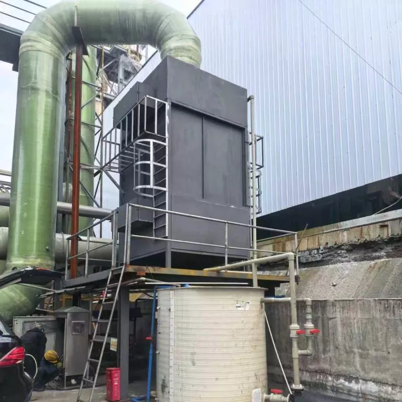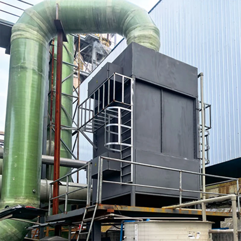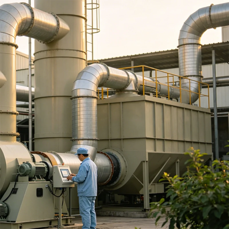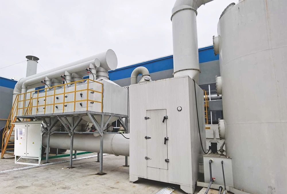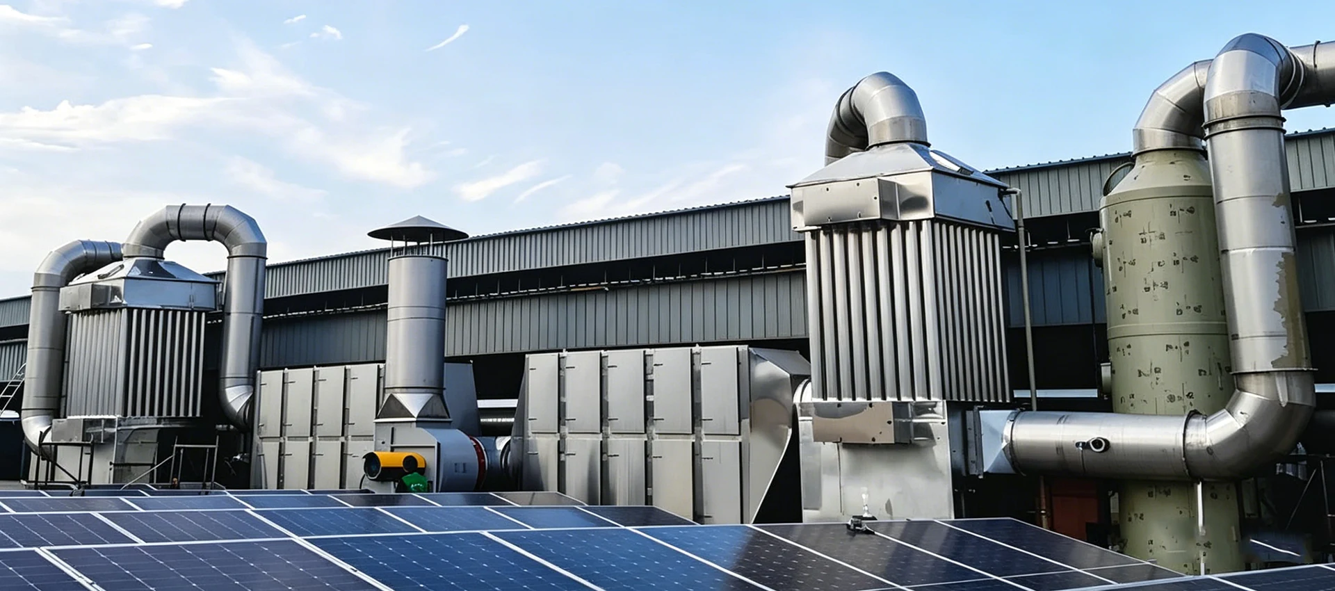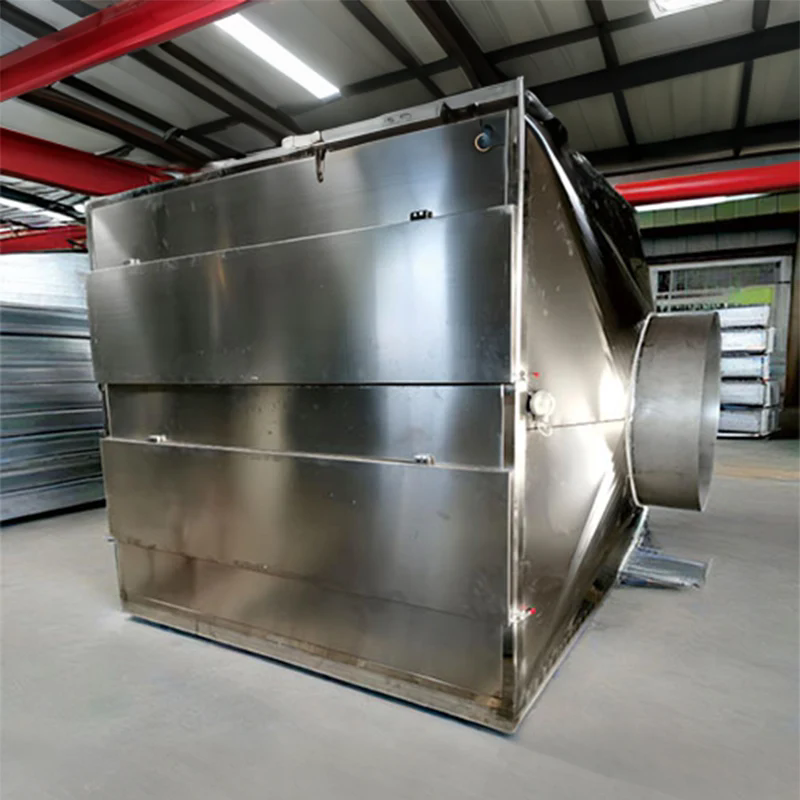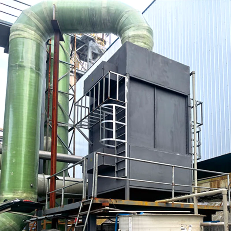
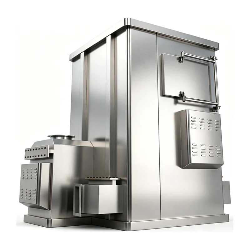
Two-Stage Heat Exchange CO Oxidation Furnace
Defaee is a professional manufacturer of industrial environmental protection equipment with rich experience in exhaust gas treatment and energy recovery. This two-stage heat exchange CO oxidation furnace features 99%+ CO conversion rate, efficient waste heat recovery and low operating cost. It is available for bulk order and custom solutions, ideal for metallurgy, chemical and building materials industries.
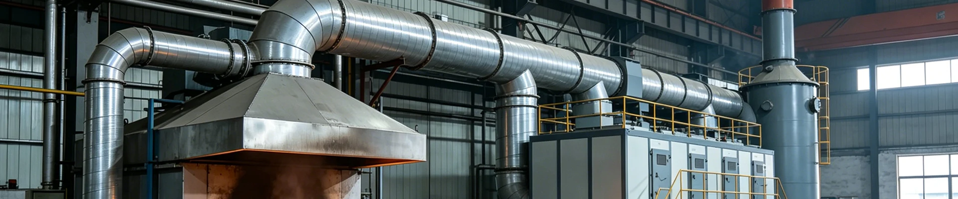
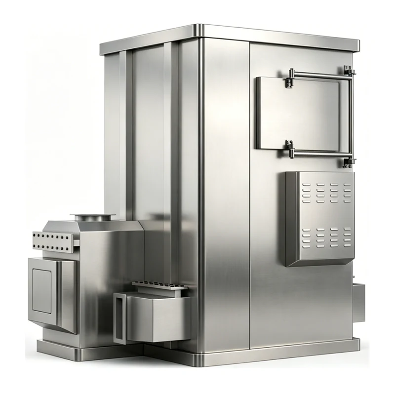
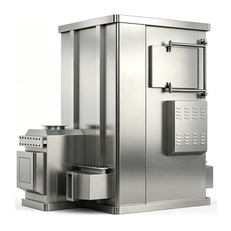
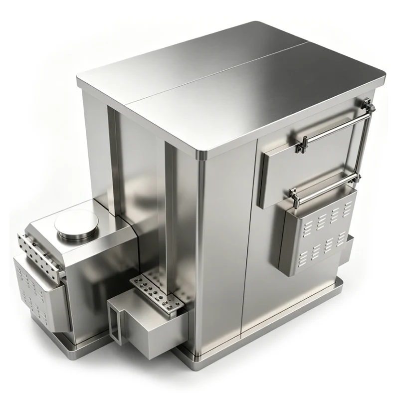
The Defaee Two-Stage Heat Exchange CO Oxidation Furnace is an integrated environmental protection and energy-saving system combining CO catalytic oxidation, two-stage high-efficiency heat recovery, low-pressure natural gas combustion, and intelligent control. It is engineered for CO-containing industrial exhaust purification and waste heat recovery in metallurgy, chemical, building materials, and related sectors.
Developed by DeFa Environmental Equipment (Ningbo) Co., Ltd. — a technology-driven manufacturer with over 20 years of expertise in high-voltage power supplies, plasma systems, and VOC abatement — this furnace uses a two-stage plate heat exchange structure to recover thermal energy from high-temperature flue gas in a stepped manner. While achieving harmless oxidation of CO, it simultaneously delivers high-efficiency thermal energy utilization. The design prioritizes environmental compliance, energy consumption reduction, and stable long-term operation.
Core Operating Principle
1. CO Catalytic Oxidation
Following pre-treatment (dust removal and fire arresting), CO-containing industrial exhaust enters the furnace reaction chamber. Under the action of noble metal catalysts (platinum-palladium), a catalytic oxidation reaction takes place at a relatively low temperature of 450–480°C, converting toxic CO into non-toxic CO₂.
Reaction: 2CO + O₂ → 2CO₂ (catalyst, 450–480°C)
This flameless process enhances operational safety and can simultaneously decompose trace volatile organic compounds (VOCs) present in the exhaust stream, helping users meet national and international emission requirements.
2. Two-Stage Heat Exchange
The built-in two-stage plate heat exchangers employ a graded cooling and gradient heat exchange design to maximize waste heat recovery from the post-reaction high-temperature flue gas:
- First-stage heat exchange: High-temperature flue gas at approximately 480°C enters the first-stage plate heat exchanger, transferring heat countercurrently to the incoming low-temperature exhaust. The flue gas temperature drops to 240–260°C, while the inlet gas is preheated to 200–220°C, reducing the natural gas energy input required for subsequent heating.
- Second-stage heat exchange: The pre-cooled flue gas then enters the second-stage heat exchanger, where it further transfers heat to fresh air or another low-temperature medium. The flue gas temperature is reduced to below 120°C, achieving a waste heat recovery rate of over 75% — significantly higher than single-stage designs.
- Temperature regulation: After heat exchange, three sets of air dampers precisely modulate the flue gas to maintain a stable discharge temperature of around 80°C, thereby avoiding equipment stress or thermal pollution caused by excessive temperature.
3. Low-Pressure Natural Gas Combustion
The system incorporates a low-pressure natural gas combustion unit, with gas supply pressure controlled at 0.02–0.05 MPa to match typical industrial low-pressure gas conditions. After precise proportioning through a pressure reducing valve, filter, and flow meter, natural gas enters the burner, mixes thoroughly with combustion air, and burns at low temperature inside the furnace to provide stable heat for the catalytic reaction.
The low-pressure combustion design eliminates the safety risks associated with high-pressure systems. Combustion efficiency exceeds 99%, while NOₓ and CO emission concentrations in the flue gas remain well below common regulatory limits. Operating costs are typically 30%–40% lower than comparable electric heating solutions.
Core Equipment Structure
1. Furnace Assembly
The furnace body is constructed with a double-layer structure: high-temperature-resistant carbon steel lined with an aluminum silicate insulation layer. The inner shell withstands temperatures up to 600°C, while the outer surface temperature is maintained at ≤50°C to minimize thermal loss. The furnace is divided into five functional sections — inlet section, preheating section, catalytic reaction section, two-stage heat exchange section, and exhaust section — and is integrally welded for excellent sealing. A built-in pressure relief port provides automatic overpressure protection.
2. Two-Stage Heat Exchange Module
The core of the heat recovery system consists of two stages of high-efficiency plate heat exchangers fabricated from 304 stainless steel, offering high temperature resistance, corrosion resistance, and reliable heat transfer performance. The exchangers are arranged in series with intermediate guide plates to ensure uniform flue gas distribution. Optimized plate spacing reduces flue gas resistance and fan energy consumption. The module is designed for easy disassembly and cleaning, accommodating exhaust streams that contain dust.
3. Low-Pressure Natural Gas Combustion System
This subsystem comprises natural gas piping, a low-pressure pressure reducing valve, gas filter, flow regulating valve, burner, ignition device, and flame detector. The pressure reducing valve stabilizes gas pressure at 0.02–0.05 MPa, while the flow valve enables precise fuel metering. A porous injection burner ensures thorough mixing of gas and air. The automatic ignition device and real-time flame detector immediately cut off the gas supply in the event of flame failure to prevent leakage.
4. Catalytic Reaction System
The system includes a catalyst bed based on a honeycomb ceramic substrate loaded with platinum-palladium noble metal catalysts, characterized by anti-poisoning properties, high temperature durability, and a typical service life of 2–3 years. At least five temperature sensors are installed within the furnace to monitor critical temperature points in real time, precisely controlling the reaction temperature within the 450–480°C window. This ensures a CO conversion rate of ≥99%.
5. Intelligent Control System
A PLC-based control system with a touch screen interface integrates temperature control, pressure monitoring, gas safety interlocks, fault alarms, and data recording. It supports fully automatic operation with one-key start/stop and automatic adjustment of gas flow and damper opening. The system continuously monitors differential pressure, gas pressure, and flame status; upon detecting any abnormality, it triggers automatic alarms and shutdown sequences. Remote monitoring and data upload functionality are also supported. The control algorithms are refined through DeFa's two decades of field data, enhancing stability and reducing the need for manual intervention.
6. Safety Auxiliary System
- Fire arrestors and dust collectors at both inlet and outlet isolate the production line from the treatment equipment and capture particulate matter, preventing flashback and clogging.
- Pressure relief port with an explosion-proof diaphragm on the top of the reaction chamber automatically releases pressure in overpressure scenarios.
- Reliable grounding of the metal enclosure with a grounding resistance ≤4Ω prevents static accumulation and electric shock hazards.
Key Performance Advantages
1. High Purification Efficiency and Compliant Emission
CO catalytic conversion rate reaches ≥99%, with CO emission concentration typically ≤50 mg/m³. Simultaneous VOC removal is achieved. The low-pressure natural gas combustion system yields NOₓ emissions ≤100 mg/m³, without black smoke or odor. Performance is validated under standard industrial conditions and aligns with regulations such as those governing air pollutants from industrial furnaces.
2. Superior Waste Heat Recovery and Energy Savings
The two-stage plate heat exchange structure achieves a waste heat recovery rate of ≥75%, reducing natural gas consumption by 20%–25% compared with single-stage heat exchange configurations. Flue gas discharge temperature is maintained at ≤120°C. Recovered heat can be utilized for inlet gas preheating, hot water supply, or facility heating, enabling cascade energy utilization.
3. Low-Pressure Operation and High Reliability
Operating on low-pressure natural gas (0.02–0.05 MPa) substantially reduces leakage risks. Multiple safety interlocks — including flameout, over-temperature, over-pressure, and grounding protection — provide comprehensive process safety. The redundant two-stage heat exchange design allows continued operation even if one stage requires maintenance.
4. Intelligent Control and Low Maintenance
Fully automatic PLC control enables unattended operation. Real-time parameter display and automatic fault diagnostics facilitate rapid troubleshooting. The detachable heat exchanger design and easily replaceable catalyst reduce maintenance effort. The overall equipment service life is rated at 10–15 years under normal operating conditions.
5. Wide Adaptability
The furnace is designed to treat industrial exhaust with CO concentrations in the range of 0.5%–5% and inlet temperatures of 100–300°C, making it suitable for blast furnace off-gas, chemical synthesis tail gas, kiln exhaust, and similar process streams. It integrates directly with standard industrial low-pressure natural gas pipelines without requiring high-pressure retrofits.
Technical Specifications (Standard Model)
|
Item |
Technical Index |
|
Treatment Air Volume |
1,000–50,000 m³/h |
|
CO Conversion Rate |
≥99% |
|
Reaction Temperature |
450–480°C |
|
Natural Gas Supply Pressure |
0.02–0.05 MPa |
|
Natural Gas Consumption |
5–50 m³/h (depending on air volume) |
|
Heat Exchange Efficiency |
≥75% |
|
Flue Gas Discharge Temperature |
≤120°C |
|
Working Pressure |
Slight negative pressure (-50 to -100 Pa) |
|
Power Supply |
380V / 50Hz |
|
Control Mode |
PLC fully automatic control |
Installation & Commissioning Guidelines
1. Installation Requirements
- Install on a flat concrete foundation with bearing capacity ≥5 t/m²; reserve at least 1.5 m of maintenance space around the equipment.
- Natural gas pipelines should use seamless steel pipes with welded connections, and must pass a tightness test (0.1 MPa, 30 min with no leakage).
- Ensure reliable equipment grounding with a yellow-green grounding wire of ≥4 mm² and grounding resistance ≤4 Ω.
- Use flexible connections at inlet and outlet ducts to prevent vibration damage.
- Install differential pressure gauges across the heat exchanger inlet and outlet to monitor fouling.
2. Commissioning Procedures
- No-load commissioning: Power on the system, start the fan and control unit; verify normal operation and accurate sensor readings.
- Gas commissioning: Introduce natural gas at low pressure; confirm no pipeline leakage, proper ignition, and stable flame.
- Load commissioning: Introduce CO-containing exhaust gas, gradually adjust gas flow and damper positions to stabilize reaction temperature at 450–480°C. After emission compliance is verified, run continuously for 24 hours.
- Interlock commissioning: Simulate flame failure, over-temperature, and over-pressure faults to verify automatic alarm and shutdown functions.
Routine Maintenance
- Daily: Check gas pressure, flame status, furnace temperature, differential pressure, and grounding; log operational data.
- Weekly: Clean the gas filter and fire arrestor; verify damper flexibility; tighten connection bolts.
- Monthly: Inspect the catalyst bed and remove any surface dust; clean heat exchanger plates to prevent clogging.
- Annually: Comprehensive inspection of insulation, heat exchangers, burner, and control system; replace aging components and calibrate sensors.
- Long-term shutdown: Close gas supply valves, purge pipeline gas, protect equipment from dust, and ventilate periodically to prevent moisture corrosion.
Applications & Value
This equipment is widely applied in CO exhaust purification for metallurgical blast furnaces, chemical synthesis processes, building material kilns, and machinery heat treatment operations. It delivers comprehensive value: environmentally compliant exhaust treatment, reduced operating costs through high-efficiency waste heat recovery, enhanced production safety via multiple protection mechanisms, and a typical investment payback period of 1–2 years through recovered thermal energy. The result is a practical combination of environmental protection and energy efficiency for industrial users.
Frequently Asked Questions
What exhaust gas conditions are suitable for this CO oxidation furnace?
The furnace is designed for industrial exhaust containing 0.5%–5% CO, with inlet temperatures typically between 100°C and 300°C. It can be applied to blast furnace gas, chemical synthesis tail gas, kiln exhaust, and similar streams containing carbon monoxide and trace VOCs.
How long does the catalyst last, and is it replaceable?
The honeycomb ceramic substrate loaded with platinum-palladium catalysts has a typical service life of 2–3 years under normal operating conditions. The catalyst module is designed for straightforward replacement, and our technical team can provide guidance on replacement intervals based on actual operating data.
What natural gas supply pressure is required?
The system operates on low-pressure natural gas with a supply pressure of 0.02–0.05 MPa, which aligns with standard industrial low-pressure gas networks. No high-pressure retrofitting is required. A pressure reducing valve, filter, and flow meter are integrated to ensure stable gas delivery.
How much energy can be saved through the two-stage heat exchange?
The two-stage plate heat exchanger achieves a waste heat recovery rate of ≥75%, reducing natural gas consumption by approximately 20%–25% compared with single-stage heat exchange configurations. Recovered heat is used to preheat the incoming exhaust gas, directly lowering the energy input needed to maintain the catalytic reaction temperature.
Is continuous unattended operation possible?
Yes. The PLC-based control system supports fully automatic operation, including one-key start/stop, real-time monitoring, and automatic adjustment of gas flow and dampers. Remote monitoring and data upload capabilities allow operators to oversee system status off-site. In case of anomalies, the system automatically initiates alarms and safe shutdown sequences.
What safety features are integrated?
Multiple safety layers are designed into the system: inlet and outlet fire arrestors prevent flashback; a pressure relief port with an explosion-proof diaphragm handles overpressure; flame detection automatically cuts off gas supply upon flameout; and reliable grounding (≤4Ω) prevents static hazards. The low-pressure combustion design itself reduces inherent risk.
What is the typical emission performance?
Under stable operating conditions, the CO conversion rate reaches ≥99%, with CO emission concentration typically ≤50 mg/m³. The low-pressure natural gas combustion system yields NOₓ emissions ≤100 mg/m³, with no black smoke or odor. Trace VOCs in the exhaust are also simultaneously decomposed.
What routine maintenance does the equipment require?
Daily checks include gas pressure, flame status, and differential pressure. Weekly tasks involve cleaning the gas filter and fire arrestor. Monthly, the catalyst bed and heat exchanger plates should be inspected and cleaned. An annual comprehensive inspection is recommended to maintain optimal performance and extend service life, which is rated at 10–15 years.
What is the typical payback period for this investment?
Most users achieve a return on investment within 1–2 years, primarily through the reduction in natural gas consumption made possible by the high-efficiency waste heat recovery system. Additional savings come from lower maintenance needs and avoided emissions penalties.
Manufacturer Expertise
DeFa Environmental Equipment (Ningbo) Co., Ltd. has dedicated over 20 years to the research, production, and application of environmental remediation and air pollution control systems. Our core competencies in high-voltage power supply technology, plasma generation, and intelligent control are embedded in every product we deliver. Serving a global customer base — with 60% of our output destined for North America — we combine rigorous engineering, certified quality processes, and continuous innovation to supply equipment that meets demanding international standards. From in-house catalyst performance testing to factory acceptance tests that simulate real operating conditions, our quality assurance practices are designed to provide reliable, long-term performance.
Hot Tags: Two-Stage Heat Exchange CO Oxidation Furnace, Manufacturer, Supplier, Factory
Send Inquiry
Contact Info
-
Address
No. 661 Cangchu Road, Jiangbei District, Ningbo City,ZHEJIANG PROVINCE,CHINA
-
Tel
-
Email
For inquiries about our products or pricelist, please leave your email to us and we will be in touch within 24 hours.