Prepared by the DeFa Engineering Team
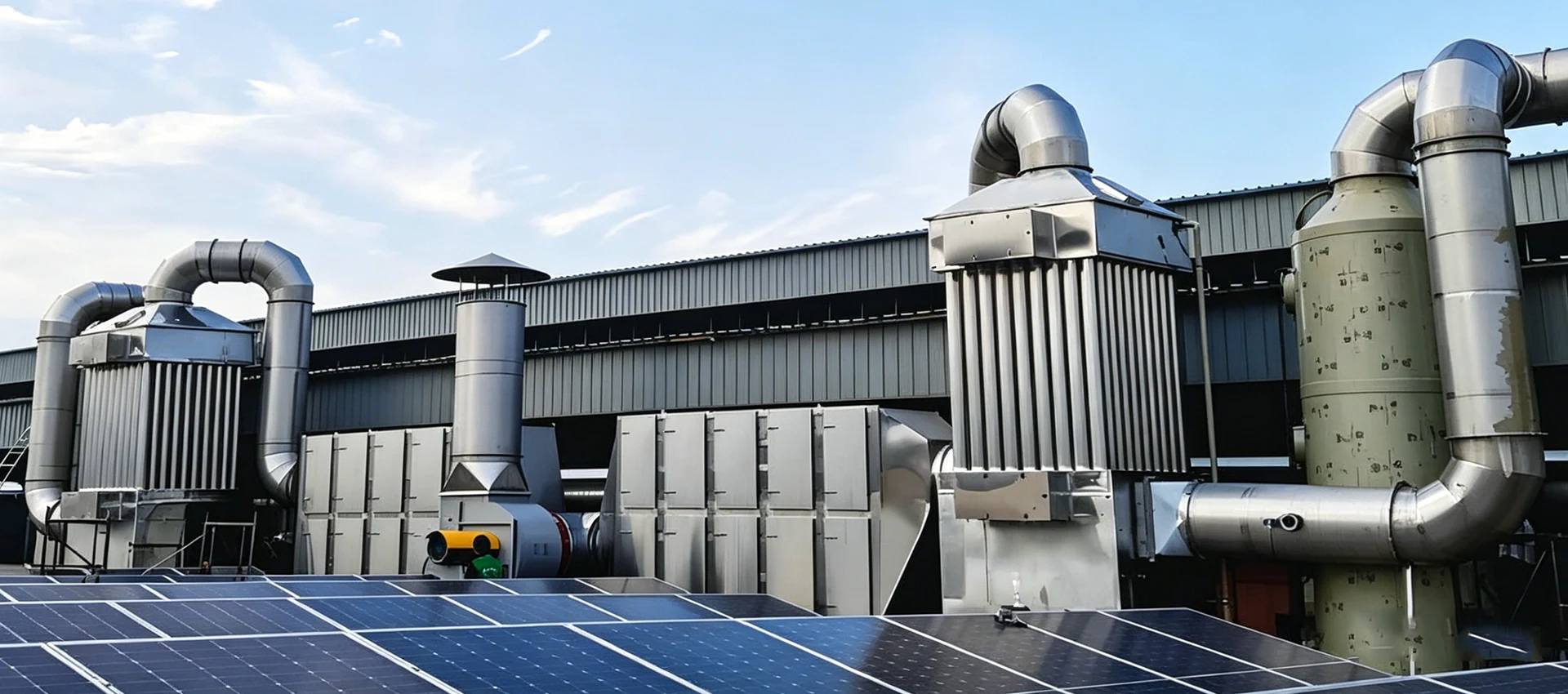
Quick answer
A zeolite rotor concentrator captures compatible VOCs from a large, dilute process-air stream. As the wheel rotates, a smaller heated desorption stream releases the adsorbed VOCs and carries them to an RTO at a higher concentration. The RTO then oxidizes the concentrated stream, while most of the main airflow leaves the adsorption section after treatment.
The combination can make sense when direct oxidation of the full airflow would waste energy. It does not reduce the incoming pollutant mass, and it is not suitable for every compound. Rotor media selection, pretreatment, humidity, gas temperature, desorption conditions, concentration peaks, lower explosive limit controls and downstream oxidizer duty must be engineered from representative process data.
Why combine a zeolite rotor concentrator with an RTO?
RTO size and energy demand are strongly affected by the gas volume that must be heated. A large ventilation stream may contain a meaningful VOC mass at a concentration too low to contribute much heat per unit of air. Sending the entire flow directly to an oxidizer can therefore create a large fan and combustion duty.
A rotor concentrator separates the airflow problem from the destruction step. It treats the large main stream by adsorption, then transfers the captured VOCs into a smaller regeneration stream. The downstream RTO handles that smaller gas volume at a higher VOC concentration.
An older but still useful U.S. EPA technical bulletin on zeolite adsorbers describes hydrophobic zeolite concentrators as temperature-swing adsorbers mounted on a rotor. EPA explains that the purpose is to reduce the airflow sent to the incinerator and increase the VOC concentration in that smaller stream. The exact concentration ratio is a project design result, not a universal setting.
How a zeolite wheel and RTO process works
- Capture and pretreatment. Process exhaust is collected and passes through the required filters, mist removal, cooling or other conditioning. Pretreatment protects the zeolite channels and reduces masking by particles or sticky material.
- Adsorption. The large VOC-laden airstream passes through the adsorption sector of the rotating wheel. Compatible VOC molecules are retained on the zeolite media while the treated main stream exits toward the stack or a polishing stage.
- Wheel rotation. The loaded sector moves gradually from the adsorption zone into a sealed desorption zone. Seals limit mixing between the large process stream and the smaller regeneration stream.
- Thermal desorption. A smaller heated airflow passes through the loaded media. Heat reduces adsorption and releases the VOCs into this regeneration stream.
- Cooling and return to adsorption. Depending on the design, a cooling section lowers the media temperature before that sector returns to the adsorption zone. Adsorption capacity generally benefits from controlled inlet and media temperature.
- RTO oxidation. The concentrated regeneration gas enters the RTO. Ceramic beds preheat the stream, the combustion chamber provides the required oxidation conditions, and the outlet bed recovers heat. See how an RTO works for the full cycle.
The EPA off-gas treatment technology report includes a schematic with a zeolite rotor, clean exhaust, concentrated stream, heat exchangers and an oxidizer. Although the report's main context is soil-vapor extraction, it notes that zeolite systems are used primarily as industrial concentrators with thermal oxidation.
Airflow concentration is not VOC removal
A concentrator does not make incoming VOC mass disappear. It redistributes most of the captured mass from a large dilute stream into a smaller concentrated stream. The oxidizer provides the destruction step.
Approximate steady-state mass balance:
VOC into rotor = VOC in treated main air + VOC sent to RTO + unaccounted accumulation or loss
The concentration ratio describes how the process airflow and desorption airflow differ. It is not the same as adsorption efficiency, overall removal efficiency or RTO destruction efficiency. Each value needs its own defined sampling locations and test method.
Use the VOC mass loading calculation guide to convert concentration and actual airflow into kg/h at the rotor inlet, treated-air outlet and RTO inlet. A mass balance can reveal bypass leakage, incomplete desorption, sampling errors or compounds that the selected media does not capture well.
Example without assuming a fixed concentration ratio
If the main process airflow is Qp and the desorption airflow is Qd, the theoretical airflow ratio is Qp ÷ Qd. The actual VOC concentration increase will be lower or different when adsorption is incomplete, seals leak, purge or cooling air mixes with the stream, or the inlet load changes. Supplier calculations should show these losses explicitly.
Which exhaust streams may fit a zeolite rotor concentrator?
The strongest preliminary candidate is usually a large-volume, low-concentration stream containing VOCs that the chosen zeolite can adsorb and release repeatedly. Stable continuous operation can help maintain predictable adsorption, desorption and downstream RTO conditions.
- Large ventilation airflow that would make direct oxidation energy-intensive
- Low or moderate VOC concentration with measurable, repeatable mass loading
- Compounds compatible with the selected zeolite pore structure and hydrophobicity
- Gas temperature and humidity that can be conditioned to the adsorption design range
- Low particle and aerosol loading after practical pretreatment
- An operating schedule long enough to justify the added rotor, fans, heat exchangers and controls
Common application discussions include coating, printing and film processes. However, industry name alone cannot confirm suitability. Solvent recipes, ovens, cleaning cycles and capture air can differ sharply between two plants in the same industry.
DeFa's air pollution control equipment overview lists zeolite rotor concentration followed by CO or RTO treatment as one option for large-airflow, low-concentration VOC streams. The final train should still be based on measured process data and a media-compatibility review.
Compounds and operating conditions that need caution
| Condition | Why it matters | Engineering response |
|---|---|---|
| Dust and fibers | Can block wheel channels, increase pressure drop and cover adsorbent surfaces | Characterize particle size and loading; select filters and access for inspection |
| Oil mist, resin or sticky aerosol | Can foul media and seals and may not desorb cleanly | Use mist control, temperature management and compound-specific testing |
| High-boiling or polymerizing compounds | May remain on the wheel, form deposits or require damaging desorption conditions | Review desorption curves, regeneration limits and cleaning strategy |
| Very volatile or weakly adsorbed compounds | May break through the adsorption sector | Select media from compound data and verify with testing where uncertainty is material |
| High humidity | Water can compete for adsorption sites depending on the zeolite and conditions | Specify hydrophobicity and evaluate dew point, temperature and seasonal extremes |
| Concentration spikes | Can overload the rotor or create an unsafe concentrated stream | Measure fast peaks; define LEL monitoring, dilution, diversion and shutdown logic |
| Halogenated, sulfur-bearing or corrosive constituents | Oxidation products may require corrosion-resistant materials or downstream scrubbing | Complete a reaction-product and materials review for normal and upset cases |
Do not rely on one total VOC reading to answer these questions. Obtain compound-specific data across representative production stages. When laboratory or pilot testing is warranted, define the inlet mixture, temperature, humidity, face velocity, adsorption time and desorption conditions so the result reflects the plant.
Design data required for a zeolite wheel + RTO system
| Input | Why the supplier needs it |
|---|---|
| Minimum, normal and maximum actual airflow | Sizes the rotor face area, fans, ducts and full system pressure drop |
| Compound list and mass fraction | Supports zeolite selection, adsorption review and oxidation-product assessment |
| Normal, peak and time-resolved VOC loading | Defines adsorption duty, desorption load and RTO heat release |
| Temperature, humidity and dew point | Influence adsorption capacity, condensation risk and conditioning needs |
| Particles, mist and condensables | Determine pretreatment and fouling risk |
| Operating schedule | Defines startup, shutdown, idle-mode and annual energy assumptions |
| Required outlet and test method | Sets adsorption, capture and destruction performance boundaries |
| Site utilities and layout | Affect fan selection, heat source, foundations, access and installation cost |
| Safety and regulatory basis | Defines concentration monitoring, interlocks, bypasses, stack testing and records |
Data should cover both average operation and credible extremes. An annual average concentration cannot size the desorption peak, and a single maximum value cannot predict annual energy use.
Energy and lifecycle cost: smaller RTO, additional concentration equipment
The main economic argument is straightforward: the RTO treats less airflow. That can reduce oxidizer size and the heat required to raise the gas to the reaction temperature. Higher VOC concentration in the desorption stream can also contribute more heat per unit of RTO airflow.
The concentrator is not free to operate. It adds pressure drop to the main stream, desorption heat, a rotor drive, seals, filters, controls, heat exchangers and maintenance access. The correct comparison is therefore:
Direct RTO lifecycle cost vs concentrator + smaller RTO lifecycle cost
- Installed cost of the rotor, RTO, pretreatment, fans, ducts and controls
- Main-stream and desorption-stream fan electricity
- Desorption heat and RTO auxiliary fuel for each operating case
- Filter, seal, drive, bearing, media and valve maintenance
- Cleaning, inspection and planned production downtime
- Acceptance testing, monitoring and waste handling
Use local utility rates and the same annual production profile for both options. Review the VOC treatment system cost guide before comparing supplier prices.
Heat integration must match real operating overlap
RTO exhaust heat may support desorption, but savings depend on temperatures, exchanger approach, control range and whether both units operate at the same time. Show the heat balance for startup, minimum load, normal production and peak load. Do not count a theoretical heat-recovery credit twice.
What to monitor and how to troubleshoot the combined system
| Area | Useful indicators | What an abnormal trend may indicate |
|---|---|---|
| Main inlet | Airflow, temperature, humidity, VOC concentration and filter differential pressure | Process change, overloaded pretreatment, condensation risk or incorrect load basis |
| Treated main air | Outlet VOC or required regulated parameter | Breakthrough, media mismatch, hot adsorption zone, seal leakage or excessive face velocity |
| Rotor | Rotation status, speed, drive load, sector pressure and seal condition | Drive fault, blockage, seal wear or airflow imbalance |
| Desorption | Airflow, inlet and outlet temperature, concentrated VOC level and LEL | Insufficient regeneration, overheating, unsafe peaks or dilution leakage |
| RTO | Chamber temperature, outlet VOC, CO, flow, oxygen, valve status and pressure | Low oxidation conditions, concentration upset, bypass leakage or switching problem |
Monitor trends across the whole train. A high stack reading may begin with poor source capture, rotor breakthrough, desorption instability or an RTO issue. Isolating one device without checking the upstream mass balance can lead to the wrong corrective action.
When direct RTO or another route may be better
A direct regenerative thermal oxidizer may be simpler when the airflow and VOC heat input already support an acceptable heat balance, or when the exhaust contains compounds that are unsuitable for the rotor but can be oxidized after effective pretreatment.
Activated carbon may deserve evaluation for intermittent low mass loading, provided breakthrough and spent-media management are addressed. Condensation or another recovery method can be attractive for a concentrated, valuable solvent. Scrubbing may be required for water-soluble gases or acid products. The industrial VOC treatment guide compares these routes by pollutant behavior and process conditions.
If the preferred downstream destruction device is still uncertain, compare RTO vs catalytic oxidizer using the concentrated desorption-stream composition, not the original dilute main stream.
Zeolite rotor concentrator + RTO RFQ checklist
- Process flow diagram and emission-source list
- Actual airflow at minimum, normal and maximum production
- Compound-specific VOC concentrations and kg/h load profile
- Gas temperature, humidity, dew point, oxygen and pressure
- Particle, mist, condensable and corrosive contaminant data
- Adsorbent type and compound-compatibility basis
- Adsorption, cooling and desorption sector arrangement
- Main-stream, desorption-stream and leakage assumptions
- Rotor speed range, seal design and access for inspection
- RTO inlet composition, load range and heat balance
- LEL monitoring, dilution, diversion, purge and shutdown logic
- Performance boundary, outlet limit and acceptance-test method
- Utility use at startup, normal load and peak load
- Maintenance tasks, spare parts and expected downtime
Build the combined system around a verified mass balance
DeFa Environmental Equipment provides industrial waste gas treatment equipment and combined VOC-control systems. Send representative compound data, airflow, load profile, temperature, humidity, contaminants and emission requirements so the team can review rotor compatibility, pretreatment and downstream oxidation duty.
Frequently asked questions
What does a zeolite rotor concentrator do?
It adsorbs compatible VOCs from a large process-air stream and releases them into a smaller heated desorption stream. This raises the VOC concentration entering the downstream RTO while reducing the airflow that the oxidizer must treat.
Does a zeolite rotor destroy VOCs?
No. The rotor is an adsorption and concentration stage. The RTO or another downstream device destroys or recovers the VOCs transferred into the desorption stream.
Is a fixed concentration ratio guaranteed?
No. The actual ratio depends on process and desorption airflow, adsorption performance, compound mixture, temperatures, humidity, media, seals and control settings. It must remain within the equipment and safety design limits.
Why is pretreatment important before a zeolite wheel?
Dust, fibers, oil mist and sticky condensables can block channels, cover adsorption surfaces or damage seals. Pretreatment protects performance and reduces cleaning and pressure-drop problems.
When is a zeolite concentrator + RTO not the best choice?
It may be unsuitable when compounds adsorb poorly, cannot be regenerated safely, foul the wheel, form corrosive oxidation products, or when the airflow and load make direct treatment simpler and less costly. A compound-specific and lifecycle review is required.