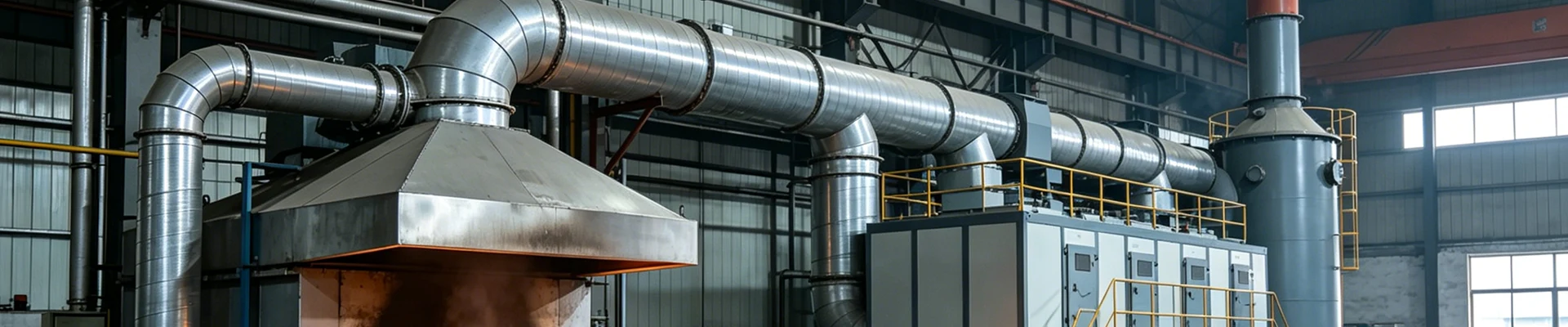
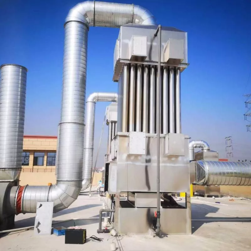
Quenching Furnace Oil Fume Purification System
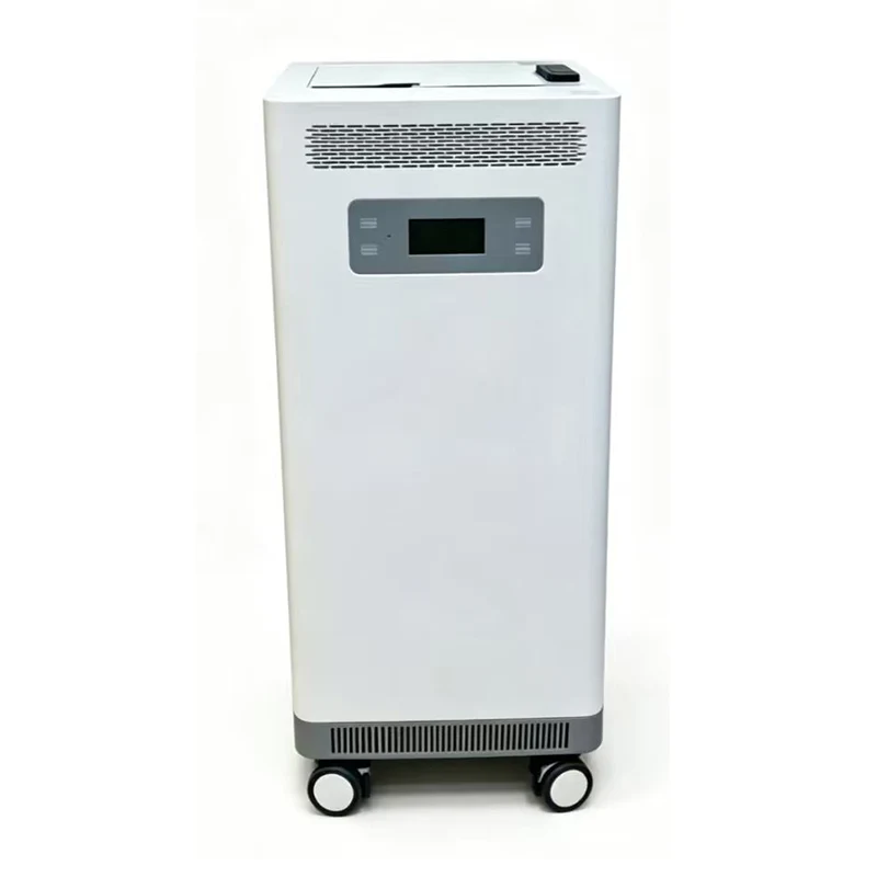
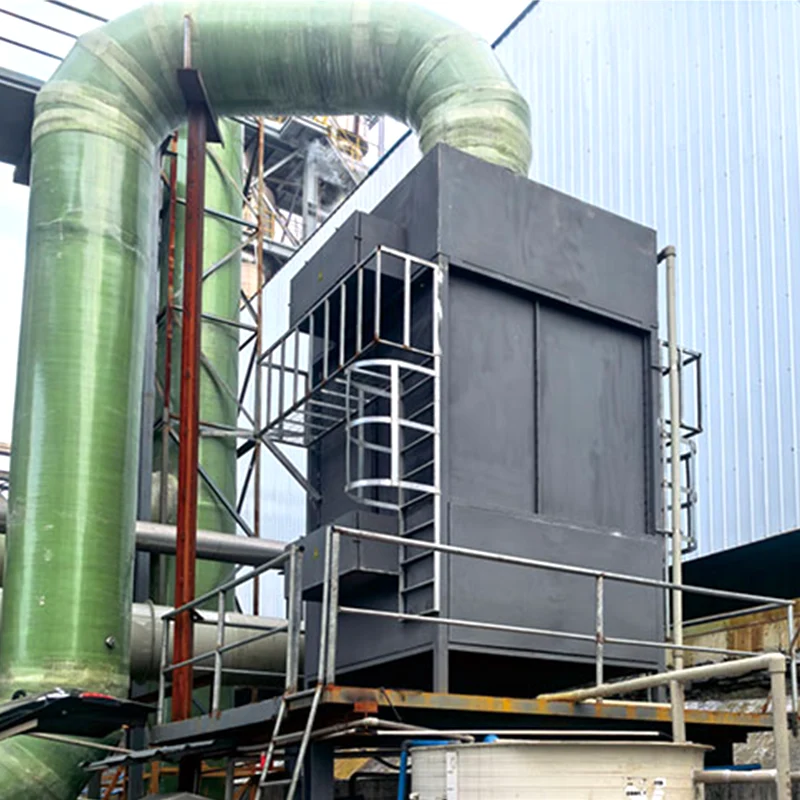
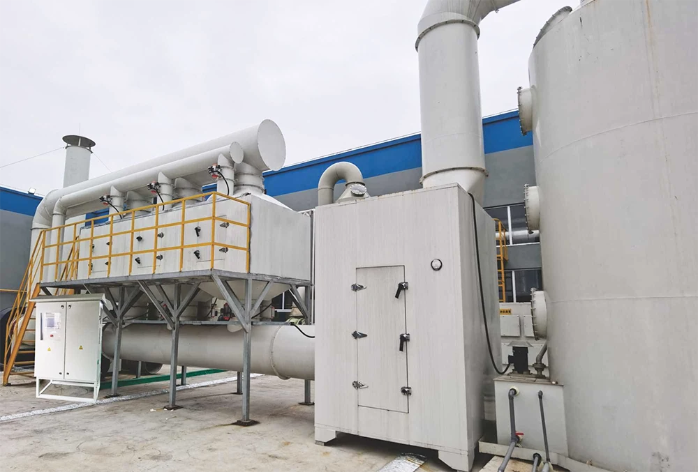
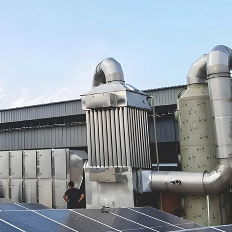
For batch quenching and heat treatment lines, DeFa Quenching Furnace Oil Fume Purification System combines pre-cooling, mechanical separation, and electrostatic precipitation to handle high-temperature oil fume and fine particles. Source, buy, or order customized systems for quenching furnaces and battery component production.
Quenching furnaces generate oil fume during the workpiece immersion and cooling stages. The fume contains high concentrations of oil vapor, fine carbonaceous particles, and combustion by-products. Its temperature fluctuates sharply, and the release is intermittent rather than continuous. These characteristics make standard oil mist collectors less effective, especially when the fume is discharged in short, intense bursts. The DeFa quenching furnace oil fume purification system is designed around these conditions, combining high-temperature pre-cooling, mechanical separation, electrostatic precipitation, and optional activated carbon adsorption.
The system is manufactured by Shengyuan Technology under the DeFa brand. It is used in heat treatment workshops serving automotive parts, bearings, gears, and new energy battery component manufacturing. The following sections describe the treatment process, technical data, configuration options, maintenance requirements, and a reference installation in the new energy battery industry.
Fume Characteristics and Treatment Approach
What Makes Quenching Fume Different
Quenching oil fume differs from continuous machining oil mist in three ways. First, the release is batch-type. A large volume of fume is produced within a short period when the workpiece enters the oil, then the generation rate drops. Second, the fume temperature is high at the source and may exceed 100°C before cooling. Third, the fume contains not only oil droplets but also fine carbon particles from partial combustion and additives in the quenching oil.
Because of these characteristics, the purification system must handle peak loads rather than average loads. The fan and pre-treatment stages are sized with this in mind.
Staged Treatment Process
- Capture: A closed hood or side-draft hood is installed at the quenching tank opening. The hood is designed to contain the fume during the immersion period without interfering with crane or manipulator movement.
- Pre-cooling: High-temperature fume passes through a cooling section. This can be an air-to-air heat exchanger, a water spray quench, or a dilution air inlet. The goal is to reduce the gas temperature below 80°C before it reaches the filter and electrostatic stages.
- Mechanical separation: A cyclone or baffle separator removes large oil droplets and carbon particles. This stage reduces the load on downstream components and captures the bulk of the oil for return to the tank or collection.
- Electrostatic precipitation: The cooled and pre-cleaned gas enters the electrostatic stage. High-voltage electrodes charge the remaining fine oil mist and carbon particles. Charged particles deposit on collection plates and drain as liquid oil.
- Activated carbon adsorption (optional): For projects with odor or VOC requirements, an activated carbon bed is installed after the electrostatic stage. This stage adsorbs residual odorous compounds and light hydrocarbons.
- Exhaust: A centrifugal fan draws the treated gas through the system and discharges it to the stack or returns it to the workshop as filtered air, depending on local requirements.
Technical Specifications
| Parameter | Standard Range |
| Airflow capacity | 2,000 m³/h to 30,000 m³/h per system, sized to quenching tank volume and batch cycle |
| Inlet fume temperature | Up to 120°C at source; pre-cooling reduces to ≤80°C before electrostatic stage |
| Inlet oil fume concentration | Peak up to 1,000 mg/m³ during immersion; average 200–500 mg/m³ |
| Outlet concentration | ≤10 mg/m³ for particulate; ≤20 mg/m³ for non-methane total hydrocarbons with carbon stage |
| Particle removal efficiency | ≥95% mechanical stage; ≥99% with electrostatic stage |
| Odor removal | ≥80% with activated carbon stage |
| System pressure drop | Mechanical + electrostatic: 800–1,200 Pa; with carbon stage: additional 300–500 Pa |
| Power supply | 380V/50Hz three-phase for fan; 6–12 kV DC for electrostatic stage |
| Fan power | 1.5 kW to 22 kW, selected for peak airflow and system resistance |
| Noise level | ≤75 dB(A) at 1 m; acoustic enclosure available for lower noise |
| Body material | Carbon steel with high-temperature coating standard; 304 stainless steel optional for corrosive fume |
| Electrode material | Stainless steel or tungsten alloy, selected for fume composition |
| Control mode | PLC with interlock to quenching furnace cycle; differential pressure monitoring; optional remote access |
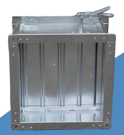
| Safety features | Over-temperature alarm, arc detection, grounding protection, fire damper at inlet (optional) |
System Components
Capture Hood
The capture hood is custom-fabricated to match the quenching tank dimensions and the movement path of the crane or manipulator. For large tanks, a push-pull ventilation arrangement may be used, with supply air jets on one side and exhaust hoods on the opposite side. The hood is designed to maintain negative pressure during the peak release period.
Pre-Cooling Section
Three cooling methods are available depending on the application:
- Air-to-air heat exchanger: Suitable for moderate temperatures and where heat recovery is desired. The recovered heat can be used for preheating or space heating.
- Water spray quench: Used for high-temperature fume. Water evaporates and absorbs heat. The resulting vapor is condensed and drained.
- Dilution air inlet: The simplest method, mixing ambient air with the hot fume. This increases total airflow and is used when heat recovery is not required.
Electrostatic Precipitator
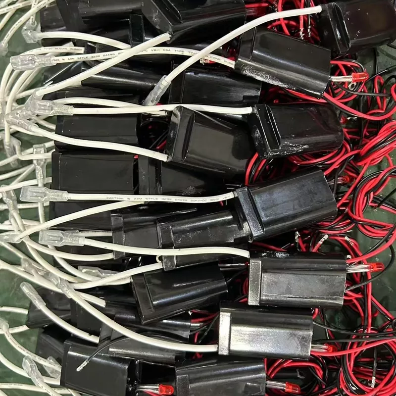
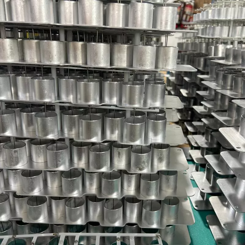
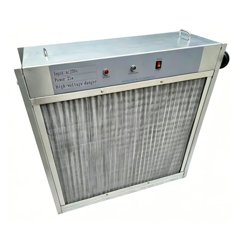
The electrostatic stage uses a two-zone design. In the ionization zone, high-voltage electrodes create a corona discharge that charges particles. In the collection zone, charged particles migrate to grounded plates and form a liquid film. The plates are periodically washed with a spray cycle to remove accumulated oil and carbon. The high-voltage power supply is current-limited and includes arc suppression to handle the fluctuating load from batch quenching.
Activated Carbon Stage (Optional)
A modular activated carbon bed is available for odor control. The carbon is contained in drawers or trays for easy replacement. The bed is sized based on airflow and the required odor removal efficiency. Spent carbon is returned to the supplier for regeneration or proper disposal.
Fan and Controls
The exhaust fan is selected with a margin for peak airflow and filter loading. It is mounted on vibration isolators and connected to the system with flexible duct connectors. The PLC control panel coordinates the fan, electrostatic power supply, and optional wash cycle. A differential pressure transmitter monitors the filter and carbon bed condition.
Applications in Heat Treatment
| Process | Fume Source | Typical Configuration |
| Batch quenching | Oil tank immersion | Closed hood + pre-cooling + electrostatic |
| Continuous quenching | Conveyor dip tank | Push-pull hood + cyclone + electrostatic |
| Vacuum quenching | Oil quench chamber exhaust | Pre-cooling + electrostatic + carbon |
| Tempering | Tempering furnace exhaust | Mechanical separator + electrostatic |
| Induction hardening | Spray quench zone | Local hood + electrostatic |
New Energy Battery Industry Reference Project
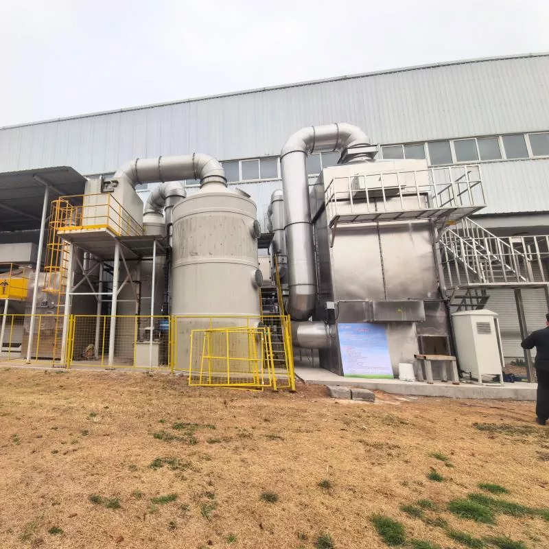
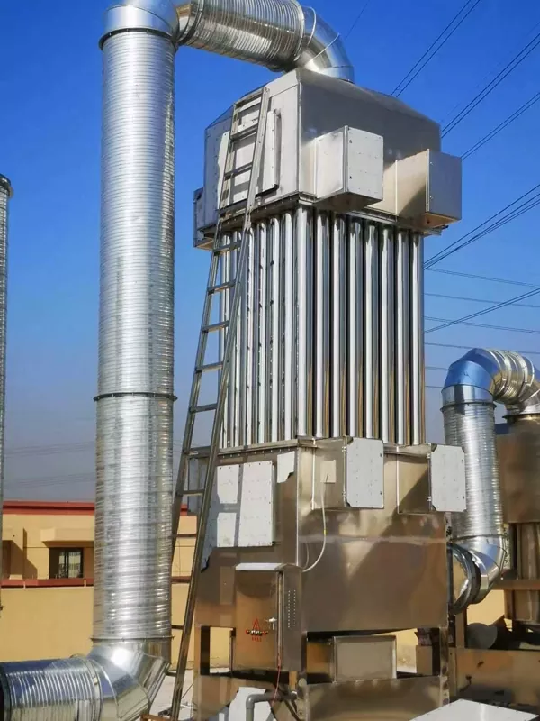
A new energy battery component manufacturer in eastern China operates batch quenching furnaces for battery casing and structural parts. The quenching tanks use high-viscosity quenching oil, and the fume contains fine carbon particles and odorous compounds. The original exhaust system discharged the fume directly through a roof stack, which led to complaints from the surrounding area and failed to meet updated emission requirements.
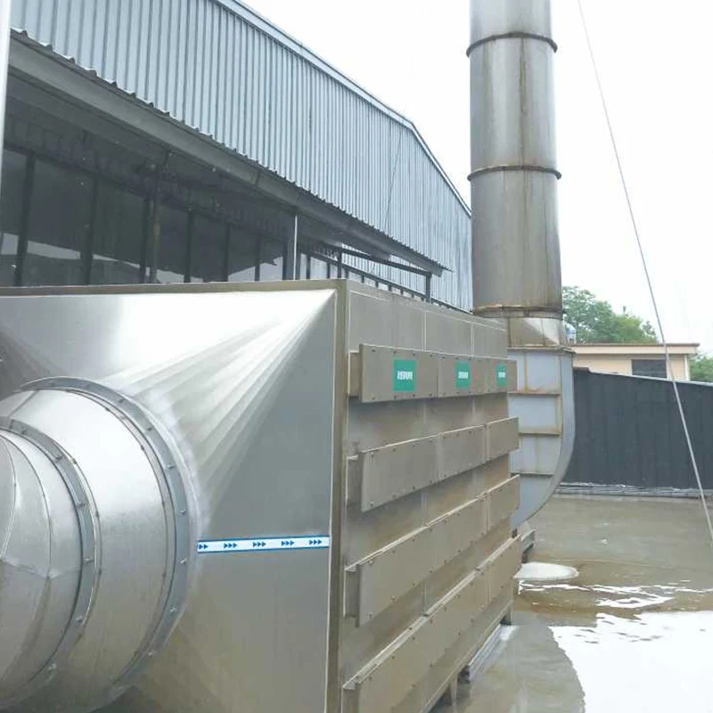
The project installed a DeFa quenching furnace oil fume purification system on two quenching lines. Each line uses a closed capture hood with a hydraulic damper that opens during the immersion cycle. The fume passes through an air-to-air pre-cooler, a cyclone separator, and a two-zone electrostatic precipitator. An activated carbon stage was added for odor control. The system is interlocked with the quenching furnace PLC so that the fan and electrostatic stages ramp up when the furnace cycle begins.
After commissioning, outlet particulate concentration measured below 8 mg/m³ and non-methane total hydrocarbons below 15 mg/m³. Odor complaints stopped. The system has operated for more than two years with scheduled maintenance. Collected oil is returned to the quenching tank after filtration, reducing oil consumption.
Installation and Commissioning
Mechanical Installation
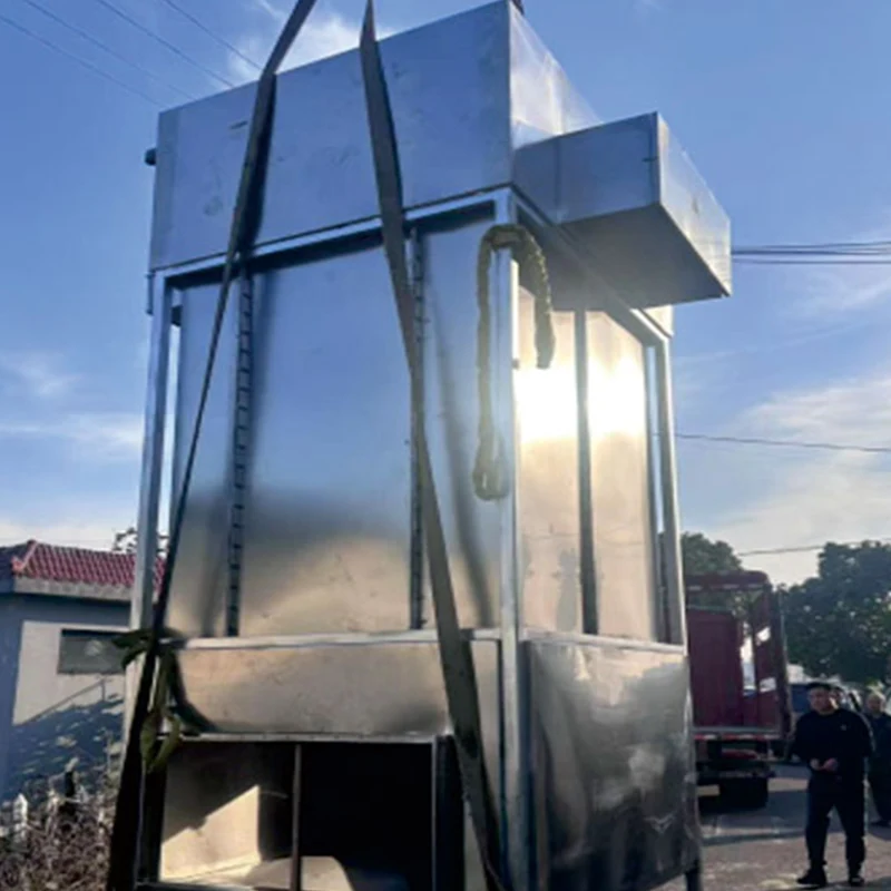
The purification system is typically installed on a steel platform adjacent to the quenching furnace or on the roof. The capture hood is mounted directly above or beside the quench tank. Ductwork between the hood and the main unit should be as short as possible and sloped toward a drain point. Access platforms are provided for maintenance of the electrostatic cells and carbon trays.
Electrical and Interlock
The control panel requires a three-phase power supply for the fan and a single-phase supply for the PLC and high-voltage power supply. The interlock signal from the quenching furnace indicates when the immersion cycle begins. This signal starts the fan and enables the electrostatic stage. After the cycle ends, the fan continues to run for a set period to purge the hood and duct.
Commissioning Checks
- Verify hood capture velocity at the tank opening using a smoke test or anemometer.
- Confirm pre-cooling outlet temperature is below 80°C.
- Test electrostatic power supply for stable output and arc response.
- Measure system pressure drop at design airflow.
- Sample outlet gas for particulate and VOC concentration after 24 hours of operation.
Maintenance Requirements
| Component | Interval | Action |
| Capture hood and damper | Weekly | Check damper operation; clean oil deposits from hood interior |
| Pre-cooler | Monthly | Inspect for fouling; clean heat exchange surfaces |
| Cyclone or mechanical separator | Monthly | Drain collected oil; inspect for blockage |
| Electrostatic collection plates | Every 1–2 months | Power off and discharge; remove and wash plates with neutral degreaser |
| High-voltage insulators | Quarterly | Clean dust and oil film; check for tracking or cracks |
| Activated carbon | Every 6–12 months | Replace or regenerate based on odor breakthrough and differential pressure |
| Fan impeller | Quarterly | Clean deposits; check balance and vibration |
| Ductwork | Every 6 months | Check for oil accumulation and corrosion; clean drain points |
Frequently Asked Questions
How is the system sized for batch quenching?
Sizing is based on the peak fume release rate, not the average. The quenching tank surface area, oil volume, workpiece weight, and immersion speed determine the peak generation rate. The capture hood and fan are sized to handle this peak. The pre-cooling and electrostatic stages are also selected for peak airflow. In some cases, a buffer volume or surge chamber is used to smooth the flow before the electrostatic stage.
Can the system handle both quenching and tempering exhaust?
Yes, but the fume characteristics differ. Quenching fume has higher oil content and larger particles. Tempering fume is usually lighter and may contain more volatile organics. A combined system can be configured with separate capture points feeding into a common purification train. The control system can adjust fan speed and electrostatic power based on which process is running.
What happens if the electrostatic stage arcs during operation?
The high-voltage power supply detects the arc and briefly interrupts output. It then automatically attempts to restore voltage. If the arc persists or the accumulated arc count exceeds a set limit, the power supply locks out and sends an alarm. This typically indicates that the collection plates need cleaning or that there is a foreign object between the electrodes. After cleaning, the system can be reset from the control panel.
Is the collected oil suitable for reuse?
In most quenching applications, the collected oil can be returned to the quench tank after filtration to remove carbon particles and metal fines. A simple settling tank or cartridge filter is sufficient. The oil should be tested periodically for viscosity, acid number, and water content to confirm it still meets the quenching process requirements.
What is the expected service life of the electrostatic components?
The high-voltage power supply is designed for a service life of 8 to 10 years under normal operating conditions. The discharge electrodes and collection plates typically last 5 to 8 years, depending on the corrosiveness of the fume and the frequency of cleaning. Replacement parts are available.
Does the system require a separate wastewater treatment for the wash water?
The wash water from cleaning the electrostatic plates contains oil and detergent. It should be directed to an oil-water separator or an existing industrial wastewater treatment system. In many cases, the oil is separated and the water is reused for the next wash cycle. The wash water is not discharged to the environment without treatment.
Can the system be installed on an existing quenching line?
Yes. The capture hood and ductwork are custom-fabricated to match the existing tank and crane layout. The main purification unit can be placed on a new platform or an available area nearby. Electrical connections and interlock signals are integrated with the existing furnace controls. Installation typically requires a short production shutdown for duct connection and commissioning.
Are there reference installations in the new energy battery industry?
Yes. A new energy battery component manufacturer in eastern China has been operating a DeFa quenching furnace oil fume purification system for over two years. The system treats fume from batch quenching of battery casing and structural parts. Outlet particulate and VOC concentrations meet local emission standards, and the project has eliminated odor complaints from nearby areas.
About DeFa
DeFa is the environmental purification equipment brand of Shengyuan Technology. The company has more than 20 years of experience in high-voltage power supplies, plasma applications, and industrial exhaust gas treatment. Its products are used in heat treatment, machining, lithium battery manufacturing, and chemical processing. The quenching furnace oil fume purification system applies the company's high-voltage power control and system integration experience to the specific challenges of batch quenching. Each system is tested for airflow, insulation, and control functions before shipment. Third-party test reports and material certificates are available upon request.
Hot Tags: Quenching Furnace Oil Fume Purification System, Manufacturer, Supplier, Factory
Send Inquiry
Contact Info
-
Address
No. 661 Cangchu Road, Jiangbei District, Ningbo City,ZHEJIANG PROVINCE,CHINA
-
Tel
-
Email
For inquiries about our products or pricelist, please leave your email to us and we will be in touch within 24 hours.